Apache
An CFA Amplifier without opamp!
Delivers a bit more than 27 Watt into 8 Ohms.
Performs well and is very fast. This is typical for CFA amplifiers.
Bandwidth is 3.5MHz.
THD is not the lowest but good enough: 0.0007%
Power supply should be a transformer 2x18VAC

An CFA Amplifier without opamp!
Delivers a bit more than 27 Watt into 8 Ohms.
Performs well and is very fast. This is typical for CFA amplifiers.
Bandwidth is 3.5MHz.
THD is not the lowest but good enough: 0.0007%
Power supply should be a transformer 2x18VAC
Last edited:

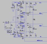
7Mhz bandwidth don't mean nothing
These go together. In a sim, THD is low because the feedback loop's bandwidth, and hence the loop gain, can be made high. In real hardware, achieving high bandwidth (shortwave frequencies) is more difficult, esp. when you consider clipping and slewing, so the compensation must be adjusted to lower the bandwidth and the loop gain - and thus increase the THD. Dropping loop BW from 7MHz to 1MHz would increase THD-1k 7 times to to 0.005% and THD-20k, to 0.1%. Meh.won't do 7ppm !
Not always , higher loop gain amps don't need to go to 7Mhz to have lots of 20Khz gain margin .
Much harder to keep phase margin >2-3Mhz. This (lineups design) must have very low gain.
The champ "wolverine" reaches unity gain well under 1.5Mhz. Still has 20db gain margin at 20Khz.
Typical VERY fast CFA (below 1) , just hits 2.2Mhz. 5PPM full power >40khz. Flat linear slope , VFA's are more logarithmic.
The Hitachi designs with (lead/lag compensation) are "bumpy" (below 2) hehe....
Typically , every CFA design on DIYA is 2-3Mhz max. VFA's are 600K - 1.5mHz. Same with all the OEM simulations.
A "Leach" type symmetrical design is more like the typical CFA , BTW.
OS
Attachments
This amplifier is also a good example of a possible separation of pre amplifier and power follower. I would reserve this for myself by being able to feed the signal from a source directly to the power amplifier in order to be able to omit the preamplifier. Most people now use very loud sources, such as DACs and CD players, which already have a high voltage amplification. The main reason is that parts modulate, alter the signal. And many parts modulate, alter the signal a lot;-)
Are there also lateral MosFets in TO-220?
Are there also lateral MosFets in TO-220?
A lot of critical voices.
Servo, yes I could do that. But there is a DC-offset adjustment = Potentiometer R4.
Ostripper opinion is more serious.
More compensation - but where do I add this?
Any other changes I could make for GainMargin and PhaseMargin?
Servo, yes I could do that. But there is a DC-offset adjustment = Potentiometer R4.
Ostripper opinion is more serious.
More compensation - but where do I add this?
Any other changes I could make for GainMargin and PhaseMargin?
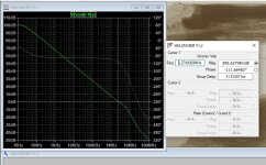
The values does not necessary be very exact, but for the circuit above
Gain Margin = 46 dB
Phase Margin = 80 Deg
Would be great if somebody else can confirm this.
It is all done by my SPICE simulations.
And we know simulations not always tell the absolute truth.
Gain Margin = 46 dB
Phase Margin = 80 Deg
Would be great if somebody else can confirm this.
It is all done by my SPICE simulations.
And we know simulations not always tell the absolute truth.
The simulation is for one point that assumes perfect matching between the current sources. The LM334Z tolerance is +/-3%. At the extremes, the offset will be 3V. I think you should fix the offset at the input.
A long time ago, I had summer jobs at IBM. I used IBM's ASTAP ("Advanced Statistical Analysis Program"). ASTAP was fast enough to simulate component variations and produce a distribution for the circuit as a whole.
Ed
A long time ago, I had summer jobs at IBM. I used IBM's ASTAP ("Advanced Statistical Analysis Program"). ASTAP was fast enough to simulate component variations and produce a distribution for the circuit as a whole.
Ed
How would you fix this?
One thing that comes in mind is to reduce 47k to 10k.
I tested to inject 20uA to increase the offset.
The offset at the input then is +1.00V
Even at this level the DC Servo will give zero DC at the output.
One thing that comes in mind is to reduce 47k to 10k.
I tested to inject 20uA to increase the offset.
The offset at the input then is +1.00V
Even at this level the DC Servo will give zero DC at the output.
I have done one of the LM334 have a variable resistor. A 10 Ohm potentiometer + other resistor.
This way one can adjust several percent for zero input offset.
This way one can adjust several percent for zero input offset.
Potentiometer R24 is for adjust input offset.
These potentiometers usually don't work well enough, because DC offset changes with temperature.
You will set it to some value, just to watch it drift away later on...
- Home
- Amplifiers
- Solid State
- Apache - Current Feedback Amplifier 27 Watt and 7 MHz