Hello,
I recently acquired a set of RCA SA-1000, 6550 push pull 100W mono blocks amplifier manufactured in 1960’
I wondered if anyone has its schematic?
The only schematic I found in DIYaudio forum was from a post in 2013 and it was very foggy.
I appreciate if anyone happen to have it and can share with me. Clear version please. Thanks!!!😊

I tried printing to PDF and tried printing out physically. Still not clear to me. Lots of application notes I cannot read. Thanks for helping out.
Anyone can share a high-res version that would be very much appreciated.
Anyone can share a high-res version that would be very much appreciated.
Printers are usually somewhat fuzzy, but the original pdf is clear enough to read.
Could you be looking at a low-res version, or is your monitor set wrong?
In the meantime you may like this:
https://www.audiovintage.fr/leforum/viewtopic.php?t=61058
Could you be looking at a low-res version, or is your monitor set wrong?
In the meantime you may like this:
https://www.audiovintage.fr/leforum/viewtopic.php?t=61058
I used your version above to print to pdf and physical print.
It’s a JPG in your attachment. Not a PDF.
I did convert it to PDF but I think because the JPG was low res so the outcome of pdf is not so great.
Do you happen to have clear PDF file that can post here? Thanks.
It’s a JPG in your attachment. Not a PDF.
I did convert it to PDF but I think because the JPG was low res so the outcome of pdf is not so great.
Do you happen to have clear PDF file that can post here? Thanks.
Unfortunately the original file available was first posted as a jpeg. Many web sites require this.
This is a "Bridging" amplifier?
Now I looked at the link that described it Post # 6.
rayma, thanks for that!
Oh, I see . . . an Un-balanced Bridging Input.
I am still learning.
Now I looked at the link that described it Post # 6.
rayma, thanks for that!
Oh, I see . . . an Un-balanced Bridging Input.
I am still learning.
Last edited:

Rayma is correct.
6A3sUMMER, this amplifier is amazing. It was built for high wattage output (100W) in push pull, and it was made for multiple purposes: public announcement, hifi high wattage in theater.
The monoblock was shipped with high frequency roll-off for PA use. To achieve true hifi (20hz to 20khz as flat as possible), a HPF wire needs to cut off (for theater back the days, or large room hifi system).
It also shipped as a standard push pull format (6EU7 input, drives 12BH7 as DC long tail splitter, then feed two 6550 running 650V B+, via capacitor coupling making this amp max output 100W PP Class AB1). This amp is versatile that it is also bridge-able to achieve higher wattage output.
The output transformer is legendary. Made and wired by RCA, with bifilar wiring and an independent negative feedback wiring that feeds into 6EU7 cathode to minimize any direct feedback from speakers with various resistance at different frequency, plus minimize speaker driver’s magnetic movement feedback coming back to the amp. It was a very common practice back then. Even McIntosh MC240 and till todays gen 6 MC275 still use independent global NFB wiring for the same reason.
I can visualize a 70V line driving 20 each 5 Watt 70V transformers and 20 speakers, in 20 classrooms.
You can hear it from the open classroom doors, all the way up and down the hallways . . .
"Teachers, please excuse all the Flag Team Girls, so they can report to the Practice Room now."
You can hear it from the open classroom doors, all the way up and down the hallways . . .
"Teachers, please excuse all the Flag Team Girls, so they can report to the Practice Room now."
Last edited:
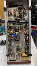
I have spent quite some time back and forth listening and modifying the circuit, since I acquired the pair about 2 months ago. This RCA SA-1000 amps have so much potential. RCA original circuit and transformers already made this amp exceptional.
I made quite a few upgrades / mods:
1. Add two stage chokes: 4H/200mA for all tubes, 10H/40mA for preamp 6EU7 and driver 12BH7A. This mod dramatically increases lo-frequency response and makes overall sound much clear and sounds wider. Note, needs to replace original power resistors and make sure DCR stays as close to original spec.
2. Add MOSFET regulated HV for G2 screen of power tube. I use 8N80C, my favorite, for any <500mA application, high voltage TO-220 package MOSFET (800V rated) with very small reversed capacitance for optimal sonic performance. This is a game changer! RCA claimed this amp is screen G2 regulated but in fact it was just supplied with CRC filter. AC ripple before the mod was measured 450mA, and <3mA after the modification!!! The result was jaw dropping! Very very solid and fast bass, and much articulated mid and high, and less harshness on top. Overall the MOSFET regulated G2 provides a way to much less distortion feeling listening experience.
3. Upgrade coupling caps to Mundorf Supreme 1.5uF MKP. My favorite and affordable luxury audiophile couple caps as always.
4. Add gold plated input RCA jack.
5. Add a toggle switch so I can bypass volume pot and use my preamp to control volume. The pot with the amp is 60-year old and can have negative effect on sound quality.
6. Replaced all 5 power filtering caps. Original was 100uF * 4 and 40uF * 1 by Mallory. I use RIFA 730uF * 4 and NCC 330uF * 1
7. Swap out negative bias capacitor - again any electric caps were replaced given their ages.
8. Add a linear 6V/3A switching power for preamp stage filament / heater. Since I like Western Electric 420a (5755) tube much better than 12AX7, I use adapters to get 420a working instead of 12AX7. The downside of 420a is its sensitivity to AC powered heater - all you hear is hum hum and HUM!
9. Add bias testing points so I can freely change the static bias. I now set to use AC130V input and B+ at 580V (plate at 575V), biased at 45mA. I use KT88, cuz I never like 6550 sound in comparison. Per KT88 datasheet, the max. Output 100W in PP is Suggested to run B+ 560V and G2 550V with total cathode current 50mA. RCA factory sets AC120V input and B+ 650V for 6550 tube, while KT88 curve operates slightly different at such high voltage. To make my kt88 live and sing longer, I required input to AC130V to lower overall HV.
10. Add customized African Padauk wood, and add customized aluminum name tag 🏷️
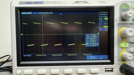
this amp is a beast and have so much potential. The frequency response is also amazing - see at 20HZ the square wave I attached.
Happy listening and DIY/modifying!
I made quite a few upgrades / mods:
1. Add two stage chokes: 4H/200mA for all tubes, 10H/40mA for preamp 6EU7 and driver 12BH7A. This mod dramatically increases lo-frequency response and makes overall sound much clear and sounds wider. Note, needs to replace original power resistors and make sure DCR stays as close to original spec.
2. Add MOSFET regulated HV for G2 screen of power tube. I use 8N80C, my favorite, for any <500mA application, high voltage TO-220 package MOSFET (800V rated) with very small reversed capacitance for optimal sonic performance. This is a game changer! RCA claimed this amp is screen G2 regulated but in fact it was just supplied with CRC filter. AC ripple before the mod was measured 450mA, and <3mA after the modification!!! The result was jaw dropping! Very very solid and fast bass, and much articulated mid and high, and less harshness on top. Overall the MOSFET regulated G2 provides a way to much less distortion feeling listening experience.
3. Upgrade coupling caps to Mundorf Supreme 1.5uF MKP. My favorite and affordable luxury audiophile couple caps as always.
4. Add gold plated input RCA jack.
5. Add a toggle switch so I can bypass volume pot and use my preamp to control volume. The pot with the amp is 60-year old and can have negative effect on sound quality.
6. Replaced all 5 power filtering caps. Original was 100uF * 4 and 40uF * 1 by Mallory. I use RIFA 730uF * 4 and NCC 330uF * 1
7. Swap out negative bias capacitor - again any electric caps were replaced given their ages.
8. Add a linear 6V/3A switching power for preamp stage filament / heater. Since I like Western Electric 420a (5755) tube much better than 12AX7, I use adapters to get 420a working instead of 12AX7. The downside of 420a is its sensitivity to AC powered heater - all you hear is hum hum and HUM!
9. Add bias testing points so I can freely change the static bias. I now set to use AC130V input and B+ at 580V (plate at 575V), biased at 45mA. I use KT88, cuz I never like 6550 sound in comparison. Per KT88 datasheet, the max. Output 100W in PP is Suggested to run B+ 560V and G2 550V with total cathode current 50mA. RCA factory sets AC120V input and B+ 650V for 6550 tube, while KT88 curve operates slightly different at such high voltage. To make my kt88 live and sing longer, I required input to AC130V to lower overall HV.
10. Add customized African Padauk wood, and add customized aluminum name tag 🏷️
this amp is a beast and have so much potential. The frequency response is also amazing - see at 20HZ the square wave I attached.
Happy listening and DIY/modifying!
Attachments

If “all you hear is hum hum and HUM” why do you like it? 😁Since I like Western Electric 420a (5755) tube much better than 12AX7, I use adapters to get 420a working instead of 12AX7. The downside of 420a is its sensitivity to AC powered heater - all you hear is hum hum and HUM!
I assume you are actually using DC heaters and are not getting all the hum, but do you like about the 420a/5755?
- Home
- Amplifiers
- Tubes / Valves
- RCA SA-1000 bridging amplifier