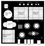
I'm building a Tubelab Simple SE and was hoping to get some feedback on the layout. I'm a bit cramped for space (13x13" aluminum chassis, with 1/2" border for fixing to the bottom). Mostly I'm wondering about the placement and orientation of the OTs, PT, and choke. From what I can tell, both the Edcor OT and Hammond PT are vertical wound, so I have them 90 deg to one another. But I'm not totally sure about the choke -- it looks to be horizontally wound, so I'm not sure if it's fine as is, or if it still needs to be rotated 90 deg with respect to the PT.
Any other thoughts would be appreciated. E.g., Should I swap the choke/motor run/PT? Are the OTs too close to each other or to the speaker outs or PCB? Any other drastic changes I should consider? (Note that the choke will be mounted underneath, and the volume and switches will be affixed to the front panel.)
Thanks!
Attachments
Maybe it's just aesthetics, but I'd prefer the IEC input, speaker connectors and input jacks on the rear panel so you can spread things out a bit on top.

Put the power supply in a separate chassis would be my recommendation. I like space. Particularly for things like better capacitors.
The choke is not pretty and is best mounted underneath. You can fix it at 45 degs there so it is not aligned with any other magnetic fields.
All of those switches (UL/FB) I would hide somewhere, e.g. behind the output transformers; it could be a disaster to accidently operate one of them when the amp is in full tilt.
The motor run cap is not particularly beautiful either and could be hidden underneath.
The RCA could come to the front or the side, to be close to the driver tube minimising the length of that cable.
What if the top was rotated 90degs clockwise, with the power traffo at the back, and OPTs on the side. Then the rectifier tube plays second fiddle to the KT88s 🙂. That would probably be the layout I would opt for now if I make another one.
Does your on/off switch include a light? If it is one of those ones with an integral neon light it could be a bit obtrusive at the front there. They are bright and they flicker. But a mains warning light is important.
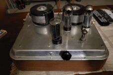
Apropos nothing in particular, since the layout is a personal choice, here was my attempt using an old baking tray 9.5" by 12". The power inlet is on the back panel, fuse is at the back on the left, RCA in on the side on the right, volume plus indicator light on the front. Switch for 8R to 4R is between the OPTs.
All of those switches (UL/FB) I would hide somewhere, e.g. behind the output transformers; it could be a disaster to accidently operate one of them when the amp is in full tilt.
The motor run cap is not particularly beautiful either and could be hidden underneath.
The RCA could come to the front or the side, to be close to the driver tube minimising the length of that cable.
What if the top was rotated 90degs clockwise, with the power traffo at the back, and OPTs on the side. Then the rectifier tube plays second fiddle to the KT88s 🙂. That would probably be the layout I would opt for now if I make another one.
Does your on/off switch include a light? If it is one of those ones with an integral neon light it could be a bit obtrusive at the front there. They are bright and they flicker. But a mains warning light is important.
Apropos nothing in particular, since the layout is a personal choice, here was my attempt using an old baking tray 9.5" by 12". The power inlet is on the back panel, fuse is at the back on the left, RCA in on the side on the right, volume plus indicator light on the front. Switch for 8R to 4R is between the OPTs.
Attachments
Last edited:
How big is your input cap, 50uF-ish? If so, that makes it an input cap filter PS and using a 750v CT PT is going to give you some really high B+ not good for a Class A operating point. You won't need a 6H choke. With the 5AR4 you'll have B+ meant for Class AB, not A. You'll need to throttle the idle current down to stay under 35W. You are falling into the same misdesign issue so many others do trying to design for a high power SE amp. A SE amp is always class A and needs to find the right place on the load line to get the best use out of big tubes. Change your PT to lower voltage at 100mA each channel.
It depends on the motor run cap. Some are in nice painted Al cans. And, the ones in unpainted Al cans can be painted. Use acid etch primer first.
Keep the Power transformer and Choke 90degrees from the OPTs if on the same level.
Keep the Power transformer and Choke 90degrees from the OPTs if on the same level.
Thanks for the suggestions so far. So would it be a bad idea to install the choke directly below the PT? Similarly, if I wanted to hide the motor run cap underneath, could this go beneath the PT or the OPTs?
Coupling between the choke and power transformer won't be significant. If it's choke input, the choke will need to be kept away from the output transformer. Keep the first cap close to the rectifier and power transformer to minimize its current loop. Other caps won't have any significant magnetic coupling.
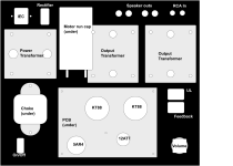
Ok here's the updated layout. I increased the width of the top panel and moved the PT back in parallel with the OPTs, primarily just for aesthetics. I have the choke and motor run caps underneath now.
I'm still not totally sure if this is a great place for the motor run cap. The schematic for the Simple SE is also attached. From what I can tell it doesn't look like it will be a problem, but any other thoughts are appeciated.
I'm still not totally sure if this is a great place for the motor run cap. The schematic for the Simple SE is also attached. From what I can tell it doesn't look like it will be a problem, but any other thoughts are appeciated.
Attachments

To check hum induction from the PT connect a headphone across the choke, connect your PT to the mains and move the choke maybe tilt it somewhat until the hum is gone. You can do the same with the OT. Connect your headphone with the primary of the OT . If you lift it you'll find a position where the hum is minimal or even absent.
I found putting a 60Hz signal from my signal generator into the choke worked nicely for determining the impact it had on the OT. I found that having the coils fire off fore and aft (both PT and chokes) worked best for me.

Motor run caps can look great on top if polished/brushed with an ultrafine scuff pad (for auto paint prep). Set pad on work bench spin cap on its top in one place without moving. Then wrap pad around cap and spin cap. No up or down movement. Want to keep the “brush marks” parallel. Wear gloves and masks… Fine aluminum dust is horrific!
Buy a cap first and try it before you finish your design to see if you like it!
Paint is also an option. This is what Thomas Mayer does with his high-end amplifiers. Painting aluminum can be difficult. Adhesion problematic: research aircraft painting.
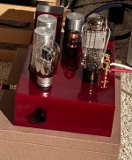
I polished the capacitors with the microfine/ultrafine scuff pads on the mono bloc amp below. Not that difficult.
Buy a cap first and try it before you finish your design to see if you like it!
Paint is also an option. This is what Thomas Mayer does with his high-end amplifiers. Painting aluminum can be difficult. Adhesion problematic: research aircraft painting.
I polished the capacitors with the microfine/ultrafine scuff pads on the mono bloc amp below. Not that difficult.
Attachments
Last edited:
If the motor run is the first capacitor in the power supply, you want to keep it in close proximity to the rectifier tube and choke. If it is not the first capacitor, there is more leeway in placement.
A cursory look at the schematics—if the motor run cap is the “auxiliary cap”, it does not appear to be the first capacitor.
I’m no expert, just advice I was given.
A cursory look at the schematics—if the motor run cap is the “auxiliary cap”, it does not appear to be the first capacitor.
I’m no expert, just advice I was given.
Last edited:
- Home
- Amplifiers
- Tubes / Valves
- Thoughts on single-ended amplifier layout