Q: Can tubes (2 final tubes in a pre-amp) share the same DC battery filament supply, assuming sufficient current and voltage from the battery? This would be using LED cathode bias. Or, I could go with filament bias. Not sure if there will be crosstalk between the tubes as they share the same DC supply. Thoughts?
A complete and accurate schematic makes things clear, and often makes answers obvious, as well as helping the answers to be correct.
DHT filamentary tubes? Probably, because you said filament bias.
Or, are they Indirect Heated tubes, with the added Cathode?
Schematic please . . .
DHT filamentary tubes? Probably, because you said filament bias.
Or, are they Indirect Heated tubes, with the added Cathode?
Schematic please . . .


There are no plate load resistors, so there is no output signal.
What kind of tubes are these?
What kind of tubes are these?
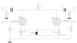
This is going to drive a solid state power amp with impedance of 10K. Attached is an updated schematic with the 50K plate resistor. I don't need much gain. Rather, I am after the tonality of the Aa tube, which is fantastic. Maybe we should consider lowering the 50K plate resistor to minimize gain? The Aa internal plate Ri = 30K. See attached schematics and Aa curves. This pre-amp is biased for 2V.
Attachments
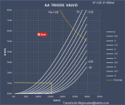
Rayma - high distortion due to? Need your expertise / advice, please. Higher voltage and more current to get in a more linear t of the curve?
Yes, the Q point is down into the curved region. The plate loads and following loads should be much higher.
Here is an example of a lower distortion design.
https://www.bartola.co.uk/valves/tag/aa-tube/
Here is an example of a lower distortion design.
https://www.bartola.co.uk/valves/tag/aa-tube/
There's a few issues I see. Typically, a triode wants to see 3-5x it's plate resistance to minimize distortion. 50K is already way too low. Next, the ROT for impedance matching between stages is a ratio of 1:10. For your 10K input impedance amp you need a preamp with an output impedance of 1K or less. This is going to be nowhere near that. Speaking of input impedance a 0.22uF cap is way too small. You will have low frequency rolloff. Think more like 10uF.
To answer your original question,yes it is typically advised to use separate floating supplies with DHT's.
Ps. You need a plate load for each tube
To answer your original question,yes it is typically advised to use separate floating supplies with DHT's.
Ps. You need a plate load for each tube
If this preamp is going to drive a power amplifier that has a low impedance 10k Ohm input, then . . .
The plate impedance, rp, that is in parallel with the 50k plate load needs to be less than 1k Ohm. Is the plate impedance less than 1 k Ohm?
The steepest plate curve I see on your graph is at 0V grid bias.
From 4mA to 5mA, from 190V to 210V.
Plate voltage changes 20V, and 1mA. 20V / 1mA = 20,000 plate impedance. That is Much larger than the needed 1k plate impedance.
You put the 50k in the wrong place.
Each plate has to have a plate load resistor between the plate and B+. (2 plate load resistors, and do not connect the plates together).
You are going to need one of two things:
Either a solid state amplifier with at least 100k Ohm input impedance . . .
Or,
Add a cathode follower that can drive a 10k Ohm input impedance solid state amplifier like the one you have.
A 4V, 0.5A filament has 8 Ohms DC resistance when warm.
You have 12V in series with 16 Ohms and 8 Ohms = 24 Ohms.
12V/24 Ohms = 0.5A so that part checks out OK (per tube).
Sorry, I had to check to get my thinker awake, it is very late, or very early here.
One end of the filament is 12V above ground, and the other end of the filament is 8V above ground.
The average bias voltage is 10V above ground (the Virtual center of the filament wire).
That means the quiescent bias of -8V is not even on your tube graph.
Keep going, you have lots to calculate, check, answer, and redesign.
Last edited:
Hi guys, thanks for the continued input. Since the Aa has a plate resistance = 30K and mu=30 (recall, I don't need the amplification, I am after tone), I am going back to use a 71A (plate resistance = 1.8K). The attached is an update schematic.
I am going to use 4.5V 0.25A for the filaments (starved). With 120V B+, I am aiming for -20V bias. Vbias = -20V = 20mA * 1000R. Sound right?
I am going to use 4.5V 0.25A for the filaments (starved). With 120V B+, I am aiming for -20V bias. Vbias = -20V = 20mA * 1000R. Sound right?
Attachments
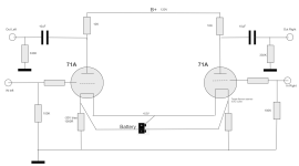
I got it all wired up. B+ is 158Vdc. Heaters are 5V. But, there is no bias and thereby, no current being drawn. Thoughts?
Attached is the schematic with measured values.

Attached is the schematic with measured values.
Last edited:
I feel that I missed something from the beginning. Firstly, you ask about a shared battery supply for the heaters. I never saw that answered, but I have used such a thing in my builds. Thread then goes from that to the amplifier design, which apparently is something that you are doing yourself? And if the heaters are 6 or 6.3 volts DC, then 5 volts may too low.
Filaments are glowing?no current being drawn. Thoughts?
Double check that anode and grid pins are correctly identified?
sidn28790,
NO continuity between filaments. ? ? ?
The 2 Larger diameter pins must have continuity, or the filaments are burned out / tube-in-box dropped, or vibrated until they opened.
I am sorry for that!
Get some more 71A tubes. Not cheap! NOS 71A are $60 at a place that I trust.
They are too expen$ive for me, but now you have me interested in purchasing 2 or 4 to do a very low power amplifier (SE or PP).
Darn! I should stop reading about other peoples projects!
Happy Projects, Happy Listening!
- Home
- Amplifiers
- Tubes / Valves
- Shared DC filament supplies