I really don't like having to reach around the back of my amps to turn them on, this was a big incentive to design this.


A 256 step relay attenuator with 0.5dB steps controlled by a touchscreen and IR remote. A Teensy 4.1 micro control unit is used to control everything, I have been playing about with this for a couple years trying to develop a really good intuitive user interface. The board was going to use a PGA2310 to do the attenuating but last week decided to use a stepped relay attenuator. The PCB ended up at 200mm x 130mm, I managed to fit 2 PSU's, 2 buffers, 2 Amyalice filters for the buffers, 230vac 15A relay for a power amp, and a relay for speaker grounding (anti-thump). It has 5 inputs, 2 outputs that will accept SE or DIFF in or out.


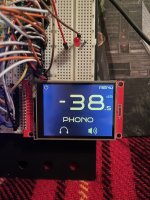
The ILI9342 is a 2.8" touchscreen display and it is really hard to take photos of it. You can change the colour of all the different elements on the screen and uses BrunoSans font. For the large gain numbers I had to edit it the font to make it work, the numbers were different widths which look good if they are static but when changing looked weird. You can also rotate the screen, adjust the brightness, adjust the backlight and calibrate the touchscreen.

The input names can be changed, I have a list of over 20 to choose from. An inputs gain can be fixed so it will work well with an input with its own volume control like a TV or computer. Another thing I added is a gain offset for low power inputs, this allows you to set the apparent gain so it matches your other inputs.

The gain can be displayed in dB or as an ascending number. The gain speed can be changed and will do 3 slow 0.5dB steps when the button is pressed before faster 1dB steps.


My schematic is a mess, I haven't had time to sort it out and I have not finished the layout. I tried to keep parts count low and used SMDs to keep the PCB as small as possible. The buffers are OPA1632 opamps with the input buffer having 3dB of gain, I will add some pads so they can be bypassed. The 8 relay attenuator has 256 0.5dB steps, I chose 5k but you could do what you want. There is a mute relay that grounds the inputs. I added 2 Amyalice filters for the analogue power, not sure if I should add one for the +5v. The analogue power is from a +-12v DC-DC converter that gets its input from the +5v psu. The +5v is from a small AC-DC converter which is mounted on the board. The Teensy 4.1 is a really powerful MCU, I thought I needed the power to update the screen at up 50fps but after optimising my code I did not need it but I am leaving it in. I have 14 UN2-5NJ non-latching relays so I decided to use them.
The IR remote works really well, they are not very responsive but with a few little tricks it is good enough. Im using the Apple Remote, it is one button short so I have programmed for the menu button when held for a second to change outputs. Left and right change inputs, play/pause does the mute, up/down does gain, menu does menu and select button does standby.
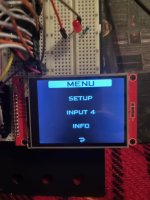
The touchscreen is supposed to be intuative and clutter free. Touching above or below the gain changes it up or down. Touching left or right of the input text changes the input. Touching a symbol or MENU will mute, change output, enter the menu or standby.
When standby is selected, mute is activated, speaker ground (NC) relay is de-energised, then all other relays are de-energised. When turning on mute is activated, the power amp relay is energised, then 2 seconds later speaker ground is energised and mute is switched off. When turned on at the mains it will enter standby. Hopefully this will be quiet and safe. In standby the standby LED is on, the display part of the touchscreen is off but the touch is active and used turn it back on.


When muted the gain numbers on the display are dimmed and the speaker symbol loses its sound waves
My breadboard is simulating the relays as you can't connect the relays easily. I have used optocouplers and LEDs to check the MCU is controlling the relays correctly (they use more power than the relays would). Apart from the relays the breadboard has the touchscreen, a standby LED, IR receiver and the Backlight control for the touchscreen. The backlight control is done with a PWM signal from the MCU and a simple analogue filter. The other components I have not tested are the 3 ULN2003LVDR, these are low voltage relay drivers that contain flyback diodes and the transistors need to operate the relays. I am happy the MCU is working as it should, not sure about my buffers and need to quadruple check my schematic and layout.
Not sure if I will use this in a preamp or as part of an integrated amp. Sorry about the dodgy schematic and bad photos.
A 256 step relay attenuator with 0.5dB steps controlled by a touchscreen and IR remote. A Teensy 4.1 micro control unit is used to control everything, I have been playing about with this for a couple years trying to develop a really good intuitive user interface. The board was going to use a PGA2310 to do the attenuating but last week decided to use a stepped relay attenuator. The PCB ended up at 200mm x 130mm, I managed to fit 2 PSU's, 2 buffers, 2 Amyalice filters for the buffers, 230vac 15A relay for a power amp, and a relay for speaker grounding (anti-thump). It has 5 inputs, 2 outputs that will accept SE or DIFF in or out.
The ILI9342 is a 2.8" touchscreen display and it is really hard to take photos of it. You can change the colour of all the different elements on the screen and uses BrunoSans font. For the large gain numbers I had to edit it the font to make it work, the numbers were different widths which look good if they are static but when changing looked weird. You can also rotate the screen, adjust the brightness, adjust the backlight and calibrate the touchscreen.
The input names can be changed, I have a list of over 20 to choose from. An inputs gain can be fixed so it will work well with an input with its own volume control like a TV or computer. Another thing I added is a gain offset for low power inputs, this allows you to set the apparent gain so it matches your other inputs.
The gain can be displayed in dB or as an ascending number. The gain speed can be changed and will do 3 slow 0.5dB steps when the button is pressed before faster 1dB steps.
My schematic is a mess, I haven't had time to sort it out and I have not finished the layout. I tried to keep parts count low and used SMDs to keep the PCB as small as possible. The buffers are OPA1632 opamps with the input buffer having 3dB of gain, I will add some pads so they can be bypassed. The 8 relay attenuator has 256 0.5dB steps, I chose 5k but you could do what you want. There is a mute relay that grounds the inputs. I added 2 Amyalice filters for the analogue power, not sure if I should add one for the +5v. The analogue power is from a +-12v DC-DC converter that gets its input from the +5v psu. The +5v is from a small AC-DC converter which is mounted on the board. The Teensy 4.1 is a really powerful MCU, I thought I needed the power to update the screen at up 50fps but after optimising my code I did not need it but I am leaving it in. I have 14 UN2-5NJ non-latching relays so I decided to use them.
The IR remote works really well, they are not very responsive but with a few little tricks it is good enough. Im using the Apple Remote, it is one button short so I have programmed for the menu button when held for a second to change outputs. Left and right change inputs, play/pause does the mute, up/down does gain, menu does menu and select button does standby.
The touchscreen is supposed to be intuative and clutter free. Touching above or below the gain changes it up or down. Touching left or right of the input text changes the input. Touching a symbol or MENU will mute, change output, enter the menu or standby.
When standby is selected, mute is activated, speaker ground (NC) relay is de-energised, then all other relays are de-energised. When turning on mute is activated, the power amp relay is energised, then 2 seconds later speaker ground is energised and mute is switched off. When turned on at the mains it will enter standby. Hopefully this will be quiet and safe. In standby the standby LED is on, the display part of the touchscreen is off but the touch is active and used turn it back on.
When muted the gain numbers on the display are dimmed and the speaker symbol loses its sound waves
My breadboard is simulating the relays as you can't connect the relays easily. I have used optocouplers and LEDs to check the MCU is controlling the relays correctly (they use more power than the relays would). Apart from the relays the breadboard has the touchscreen, a standby LED, IR receiver and the Backlight control for the touchscreen. The backlight control is done with a PWM signal from the MCU and a simple analogue filter. The other components I have not tested are the 3 ULN2003LVDR, these are low voltage relay drivers that contain flyback diodes and the transistors need to operate the relays. I am happy the MCU is working as it should, not sure about my buffers and need to quadruple check my schematic and layout.
Not sure if I will use this in a preamp or as part of an integrated amp. Sorry about the dodgy schematic and bad photos.
Attachments
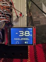


The display pictures were awful in the original post so I went in a dark room and messed about with the exposure and got a better one. It does show the background as black, in the other photos the camera made the background look light. Look at it on your phone and it will be about the right size.

I tidied the schematic and added some through holes to bypass the input and output buffers. If the AC-DC and DC-DC converters were not fitted it would be possible to easily wire in different power supplies.


I used AMB.org to get the restore values (Resistor Value Calculator) and will add matching references to them on the board to make it easier to use different values..
I tidied the schematic and added some through holes to bypass the input and output buffers. If the AC-DC and DC-DC converters were not fitted it would be possible to easily wire in different power supplies.
I used AMB.org to get the restore values (Resistor Value Calculator) and will add matching references to them on the board to make it easier to use different values..
I've been working on my attenuator, making the schematic legible and improving the display. The menu has been cut down to backlight, screen colours, gain speed and 3 input settings. I have changed the way the gain is displayed so I don't need to use a custom font. The Menu, Mute and Output touchscreen controls only appear on the display when it is touched for a cleaner look.


The PCB also has a few changes. All the MCU pins that were unused or to the display can now be accessed by a pin socket so a different type of screen and 10 spare pins could be used in the future. The board is now 200mm x 110mm. The schematic has been split into analog and digital, I have also used connection references so there is no need to follow traces.


I am not 100% sure my buffers are correct, for the OPA1632 1V in will give 500mV out if the input and feedback resistors are the some value I think ???? I want 3db gain from the input buff and 0db gain.
The PCB also has a few changes. All the MCU pins that were unused or to the display can now be accessed by a pin socket so a different type of screen and 10 spare pins could be used in the future. The board is now 200mm x 110mm. The schematic has been split into analog and digital, I have also used connection references so there is no need to follow traces.
I am not 100% sure my buffers are correct, for the OPA1632 1V in will give 500mV out if the input and feedback resistors are the some value I think ???? I want 3db gain from the input buff and 0db gain.
Last edited:
A heads-up: page 13 of the spec sheet has this gotcha:
So if the unit starts acting up you might want to look into this.
If a current is applied to the coil over a long period of time, the coil temperature rises, promoting generation of organic
gas inside the relay, which may result in faulty contacts. In this case, use of a latching relay is recommended.
So if the unit starts acting up you might want to look into this.
I will have to look into this gas. I was also thinking of trying a variable H-pad using relays, but my simulations show it is not very good at lower attenuation.
- Home
- Amplifiers
- Pass Labs
- Relay Attenuator for my XA252