Hi,
I was looking for a bit of advice. I have the above receiver where everything works except for the tuner part.
It has an AM and FM section, with both sides just producing white noise. On occasion with the AM (on medium wave) selected I can hear a faint radio station.
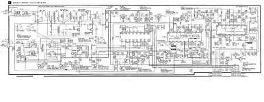
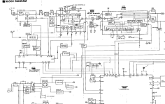
I have attached the block diagram and schematic - the service manual is easily downloaded, with the 9MB being better quality.
My thinking is there is a problem with the circuit where both AM and FM come together, and that there is probably no issue with alignment or the oscillators as they both have different ones. I am slightly optimistic that at least the AM is picking up something as I can hear a very faint station in amongst the hiss and crackle. So I think at least one of the front ends must work.
I think both FM and AM first come together on IC201 (AN7273A) - FM/AM IF AMP, DET and AM mixer. AM comes in on pin 3 and FM on pin 1. The output is on pin 13. If I put a 1V 1KHz sinewave on pin 13, I hear the tone amongst the noise, so I assume everything after IC201 is ok. I am wondering if the IC is the problem ? Is there any way to test if that is the case ? I tried bridging pins 1 and 3 to 13 with a 0.3uF capacitor but got nothing, but then the signal would not be 'processed' or amplified. I have got an old analogue scope, which does not pick up much on pins 1 and 3, I am not sure what frequency or what voltage I would expect.
I can pick up a AN7273 (not sure if an 'A' or not) on ebay for £5, but it would be nice to prove the chip is the problem first, or investigate other things on the PCB.
The voltages coming in (15.5V and 5.5V) are there.
This is the first tuner I have attempted to repair, so have spent the last week reading round the subject, but am now looking for a bit of advice from the more experienced.
Cheers !
I was looking for a bit of advice. I have the above receiver where everything works except for the tuner part.
It has an AM and FM section, with both sides just producing white noise. On occasion with the AM (on medium wave) selected I can hear a faint radio station.
I have attached the block diagram and schematic - the service manual is easily downloaded, with the 9MB being better quality.
My thinking is there is a problem with the circuit where both AM and FM come together, and that there is probably no issue with alignment or the oscillators as they both have different ones. I am slightly optimistic that at least the AM is picking up something as I can hear a very faint station in amongst the hiss and crackle. So I think at least one of the front ends must work.
I think both FM and AM first come together on IC201 (AN7273A) - FM/AM IF AMP, DET and AM mixer. AM comes in on pin 3 and FM on pin 1. The output is on pin 13. If I put a 1V 1KHz sinewave on pin 13, I hear the tone amongst the noise, so I assume everything after IC201 is ok. I am wondering if the IC is the problem ? Is there any way to test if that is the case ? I tried bridging pins 1 and 3 to 13 with a 0.3uF capacitor but got nothing, but then the signal would not be 'processed' or amplified. I have got an old analogue scope, which does not pick up much on pins 1 and 3, I am not sure what frequency or what voltage I would expect.
I can pick up a AN7273 (not sure if an 'A' or not) on ebay for £5, but it would be nice to prove the chip is the problem first, or investigate other things on the PCB.
The voltages coming in (15.5V and 5.5V) are there.
This is the first tuner I have attempted to repair, so have spent the last week reading round the subject, but am now looking for a bit of advice from the more experienced.
Cheers !
Attachments
Hi. If you have another fm radio , even portable , you can transfer if sigal 10,7Mhz to this tuner ic filters and check if ic is working ok. Rf or antenna cable should be used, and through capacitor kinda 10nf , also existing filter maybe desoldered or track cut , to prevent two signals mixed together.
Thanks for the quick reply. I think I have a portable FM radio somewhere.
Would I put the IF from that (if I can work out where it is !) onto pin 1 of the AN7273 ?
Would I put the IF from that (if I can work out where it is !) onto pin 1 of the AN7273 ?
Yes, if it would be easier. I mean desolder pin1 from board, and solder small capacitor , and rf cable to another leg of capacitor. But i think desolder filter with 3 legs easier. If it works , the you can move left, according schematic. If not work, then check inductor with dmm, if not open. Have read that some old inductors get bad,.no dc resistance, open.
Ok, so I found an old FM radio from the late 80s, and found the IF feed into the TA7640AP IC on pin 15.

I then took this via a coaxial cable and 10nF capacitor and put it in on pin 1 of the Technics receiver AN7273, selected FM and.....
got nothing. I checked my 'contraption' by then touching the coaxial back on pin 15, and got FM on my working ghetto blaster, albeit not great quality. I grounded each end of the coaxial to the chassis of each machine. So it looks like it is some thing further back which affects both Am and FM. But I'm not sure the AM and FM have anything in common prior to IC201. The only thing I can see is the FM/AM loop filter, which might rely on Q101 and Q102 working. I think they are both under the shield.
I may investigate if I can increase the strength of the signal on the ghetto blaster, it was quite hard to dismantle to get to the PCB - the antenna is currently joined by a crocodile clip. I will reverse the bypass and check the signal is ok.
Strange. If both bands are affected, it may be too low supply voltage for AN ic. Also interesting looking filter z202, but it's for AM. I would check dc resistance of all inductors t201 t202 . Recently got to check and repair old tuner, problem was missing stereo. And solution was to install adjustment ferrite, fm detector's inductor had no ferrite , I don't know if it was supposed to be so. Inserted matching ferrite, sound become louder, adjusted for best, and stereo was back. Very strange. Don't remember now what ic had this tuner.
Also ,in your schematic i see signal going through switch q204 amd L324, also electrolytic cap is in series. Try to bypass all this with 1uf film capacitor , maybe sound ,or white noise will appear?
Also ,in your schematic i see signal going through switch q204 amd L324, also electrolytic cap is in series. Try to bypass all this with 1uf film capacitor , maybe sound ,or white noise will appear?
Update - finally got this working.
Bought a few am and fm kit radios, to learn how they work and how to test each part.
AM part worked with a proper AM antenna.
The FM front end had no oscillator output on pin 8. With a signal generator at the IF of 10MHz and waving the lead over the IF filters CF201 and CF202, I could hear my 1kHz signal. Poked around the FM front end and found that one leg of the centre tapped inductor in the oscillator circuit had a dry joint, and resoldering fixed it.
Thanks for the input everyone.
Only took me 6 months…..
- Home
- Source & Line
- Analogue Source
- Technics SA-GX230 Receiver - Tuner not working