Im trying to figure out what kind of circuit can affect to q of a subwoofer system as described in the paper attached

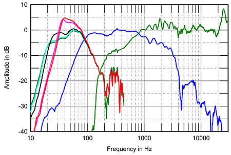
Fig.4 Vandersteen Model Seven, acoustic crossover on upper-midrange axis at 50", corrected for microphone response, with nearfield responses of upper-midrange unit (green) and lower-midrange unit (blue), both plotted below 350Hz and taken with high-pass filter in-circuit. Nearfield response of powered woofer shown with Contour set to: "1" (green), "4" (cyan), "7" (black), "9" (magenta), "10" (red).
To the left of fig.4 are shown the powered woofer's output, with its Contour control set to "1" (green trace), "4" (cyan), "7" (black), "9" (magenta), and "10" (red). (The 11 bandpass equalizer pots were set to their central, flat positions for these measurements.) The Contour control adjusts not only the amount of midbass boost but the low-frequency cutoff. Peculiarly, the biggest response changes occur when the control is set between "7" and "10"; a light hand on this control will be necessary. I set the woofer-level control to give an apparent crossover of 90Hz, but it should be noted that there is plenty of woofer gain still available. Again, a light hand on this control will be necessary to get the best match of speaker and room.
.jpg")
Fig.4 Vandersteen Model Seven, acoustic crossover on upper-midrange axis at 50", corrected for microphone response, with nearfield responses of upper-midrange unit (green) and lower-midrange unit (blue), both plotted below 350Hz and taken with high-pass filter in-circuit. Nearfield response of powered woofer shown with Contour set to: "1" (green), "4" (cyan), "7" (black), "9" (magenta), "10" (red).
To the left of fig.4 are shown the powered woofer's output, with its Contour control set to "1" (green trace), "4" (cyan), "7" (black), "9" (magenta), and "10" (red). (The 11 bandpass equalizer pots were set to their central, flat positions for these measurements.) The Contour control adjusts not only the amount of midbass boost but the low-frequency cutoff. Peculiarly, the biggest response changes occur when the control is set between "7" and "10"; a light hand on this control will be necessary. I set the woofer-level control to give an apparent crossover of 90Hz, but it should be noted that there is plenty of woofer gain still available. Again, a light hand on this control will be necessary to get the best match of speaker and room.
Attachments
Last edited:
Two things come to mind, no idea if either is applicable as I don't know what a Model Five is:
Linkwitz transform circuit or some other kind of biquad used to cover the poles of the subwoofer with zeros while placing new poles somewhere else.
Main amplifier with series and shunt feedback at the output.
Linkwitz transform circuit or some other kind of biquad used to cover the poles of the subwoofer with zeros while placing new poles somewhere else.
Main amplifier with series and shunt feedback at the output.
The article is truncated from the top, and maybe there's a follow up beyond.
Like puzzles, but now this?
Vandersteen Audio... Belgium I guess.
Like puzzles, but now this?
Vandersteen Audio... Belgium I guess.
Fig.4 Vandersteen Model Seven, acoustic crossover on upper-midrange axis at 50", corrected for microphone response, with nearfield responses of upper-midrange unit (green) and lower-midrange unit (blue), both plotted below 350Hz and taken with high-pass filter in-circuit. Nearfield response of powered woofer shown with Contour set to: "1" (green), "4" (cyan), "7" (black), "9" (magenta), "10" (red).
To the left of fig.4 are shown the powered woofer's output, with its Contour control set to "1" (green trace), "4" (cyan), "7" (black), "9" (magenta), and "10" (red). (The 11 bandpass equalizer pots were set to their central, flat positions for these measurements.) The Contour control adjusts not only the amount of midbass boost but the low-frequency cutoff. Peculiarly, the biggest response changes occur when the control is set between "7" and "10"; a light hand on this control will be necessary. I set the woofer-level control to give an apparent crossover of 90Hz, but it should be noted that there is plenty of woofer gain still available. Again, a light hand on this control will be necessary to get the best match of speaker and room.
Here is an article that explains bass EQ.
Electronic Bass Boost for Woofers
Popular Electronics Nov 1981
http://www.cieri.net/Area protetta/Progetti/Electronic Bass Boost for Woofers.pdf
Ed
Electronic Bass Boost for Woofers
Popular Electronics Nov 1981
http://www.cieri.net/Area protetta/Progetti/Electronic Bass Boost for Woofers.pdf
Ed

This is what I was able to trace out so far there are two other lines to the amp section. Im assuming those are mostly just 11 and eq stuff. This seems to be most of whats involved in the contour knob

Maybe something like the following idealized model created using VituixCAD will help to shed some light. It models the woofer as a 2nd-order high-pass filter with Q = 1 and resonance frequency of 40Hz. This would result in the driver having a peak in its response. However, there is a preceding high-pass 2nd-order shaping filter also in place, whose Q setting can be varied and whose resonance frequency is set to 50Hz. Additional variation can be introduced by varying the resonance frequency of the shaping filter as well.

The response obtained using this model with Q = 0.5 for the variable filter is shown below.

If we change the Q to 0.71 for the variable filter, we get the following response.

If we change the Q to 1.0 for the variable filter, we get the following response.

The response obtained using this model with Q = 0.5 for the variable filter is shown below.
If we change the Q to 0.71 for the variable filter, we get the following response.
If we change the Q to 1.0 for the variable filter, we get the following response.
Last edited:
- Home
- Design & Build
- Electronic Design
- What kind of filter is this???