I found the undergraduate course materials online about PID controller, Lead/Lag/Lead-Lag compensator and I thought they’re interesting as they have some keywords related to our DIY speakers, i.e., Minimum phase, Phase Margin, Bode plot, Nyquist plot, Quality factor, etc. Apart from the PID, Lead/Lag methods, I’m certain there are people here already using Pole-Zero method in designing loudspeakers.
Is there anyone using PID controller, Lead/Lag/Lead-Lag compensator in designing loudspeakers? If so, could you please share your experience? A brief design procedure will be appreciated.
Note: Although I didn’t graduate electrical engineering, but industrial, I believe I could try to understand them.
This is better known as motional feedback or MFB.
https://en.wikipedia.org/wiki/Motional_Feedback
It is a basic feedback controller on the excursion of a woofer cone. There have been several threads on this topic.
More info
https://rmsacoustics.nl/activecontrol.html
https://rmsacoustics.nl/audiodesign.html
https://en.wikipedia.org/wiki/Motional_Feedback
It is a basic feedback controller on the excursion of a woofer cone. There have been several threads on this topic.
More info
https://rmsacoustics.nl/activecontrol.html
https://rmsacoustics.nl/audiodesign.html
Equalisation is a kind of pole-zero compensation of the plant (loudspeaker in this case), with the processor being the compensator.I’m certain there are people here already using Pole-Zero method in designing loudspeakers.
The high/low shelving filters often used to EQ the higher end of compression driver responses are in fact lead/lag compensators.Is there anyone using PID controller, Lead/Lag/Lead-Lag compensator in designing loudspeakers?
Yes, the theoretical design of crossovers is based on such analysis.
https://www.linkwitzlab.com/crossovers.htm
https://www.linkwitzlab.com/crossovers.htm
Read 'parametric equalisation' or PEQ ....Equalisation is a kind of pole-zero compensation of the plant ...
The shelving filters are also shown here:
https://www.linkwitzlab.com/filters.htm#5
A PID controller is usually used to make an output follow changes in a set point input. An example could be a controller that makes an IR oven track the prescribed reflow temperature profile of solder.Is there anyone using PID controller, Lead/Lag/Lead-Lag compensator in designing loudspeakers? If so, could you please share your experience? A brief design procedure will be appreciated.
Speakers usually operate open loop. You apply a voltage to them and hope for the best. The amplifier would have a control loop and one could conceivably use a PID controller there – assuming it's fast enough. Many of the compensation techniques used in amplifiers are the same as the P, I, and D used in PID controllers.
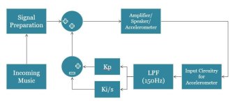
There have been some attempts to wrap a control loop around a speaker, though. Two of my friends in college did that. They took a KEF B139 and attached an accelerometer to the front of it. They then used a control loop in an attempt to control the position of the (piston) cone as function of the applied voltage. I recall they ran into some stability issues with that.
Another approach is to use a speaker driver with two voice coils. You'd then use one voice coil as a sense coil and control the speaker cone that way.
Yet other ways involve using laser interferometry to measure the position of the speaker cone so it can be controlled electrically.
PID controllers could potentially be useful there. Doing so would require that the P, I, and D parameters are optimized, though. That's usually not a trivial task.
Tom
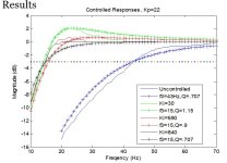
I did this in college with a subwoofer. I had to add an LPF to make it stable.There have been some attempts to wrap a control loop around a speaker, though. Two of my friends in college did that. They took a KEF B139 and attached an accelerometer to the front of it. They then used a control loop in an attempt to control the position of the (piston) cone as function of the applied voltage. I recall they ran into some stability issues with that.


Rythmik’s servo technology is a specific implementation of a similar principle: https://www.rythmikaudio.com/DirectServo.html

"Servo-controlled" subwoofers use a feedback mechanism where the actual motion of the speaker cone is measured (often with an accelerometer or similar sensor) and compared to the input signal. The system then makes real-time adjustments to the amplifier signal to correct any deviations.
Servo systems are "allegedly" known for producing very low distortion, as they can correct for non-linearities in the driver’s response, ensuring that the cone movement closely matches the audio signal. CHIFI so YMMV...
Last edited:
You would never use PID though. PID controllers became standardized because they covered the most common control actions required for setpoint and load changes AND they could be implemented entirely in analog which is what dominated until the 80's. If you were going to this, you would use digital and that would open up a host of control alogorithms better suited to the application.
I do not know how you would apply a proportional integro-differential controller to a speaker system. Has that been done before?I found the undergraduate course materials online about PID controller, Lead/Lag/Lead-Lag compensator and I thought they’re interesting as they have some keywords related to our DIY speakers, i.e., Minimum phase, Phase Margin, Bode plot, Nyquist plot, Quality factor, etc. Apart from the PID, Lead/Lag methods, I’m certain there are people here already using Pole-Zero method in designing loudspeakers.
Is there anyone using PID controller, Lead/Lag/Lead-Lag compensator in designing loudspeakers? If so, could you please share your experience? A brief design procedure will be appreciated.
Note: Although I didn’t graduate electrical engineering, but industrial, I believe I could try to understand them.
- Home
- Loudspeakers
- Multi-Way
- PID controller, Lead/Lag compensator for loudspeaker