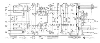
Hi all, looking at the circuit of the Neumann WV2 phono stage, I ran into some inconsistencies..... The circuit has an input transformer 1:50, gain stage EF804S (triode connected), a second gain stage with EF804S and RIAA section as a feedback circuit around it, then another gain stage with E80CC, and a fourth gain stage with another E80CC and feedback, then an output transformer 10:1.
When looking at the operating conditions (very low current), and calculating the gain of the different stages, the total gain including everything ends up at a whopping 91dB @ 1kHz:
input transformer +26dB
first gain stage +30dB (using the values from the datasheet)
RIAA stage +15dB (at 1kHz) (again, using datasheet values)
third gain stage +20dB
fourth gain stage +15dB
output transformer -14dB (output is symmetrical)
The simulation kind of confirms those values, with some dB of differences, most likely due to the tubes being operated at very low plate current and the tube model may or may not be very accurate in that area. (I used a 6922 in place of the E80CC).
The description of the phono stage is talking about a gain of 70dB (with input transformer in ) or 50dB (without), which is quite a difference.
Anybody has a good idea where that big difference is coming from?
Attachments
Generic MC pickup has about 20dB lesser output voltage, than MM pickup.
If you have 50dB gain MM phono stage, must to use another 20dB gain for MC, like 1:10 SUT.
If you have 50dB gain MM phono stage, must to use another 20dB gain for MC, like 1:10 SUT.

yes I know. My question is: Why is the manual stating 70dB gain, while calculation and simulation give 91dB?
I am pretty sure that Neumann did measure their preamps and that they match their specification, the error must be elsewhere......
I am pretty sure that Neumann did measure their preamps and that they match their specification, the error must be elsewhere......
91dB is nonsense for phono! 😳
Is your calculation from SUT aided phono, or with phono + playback "power" amp?
20-21dB for power amp is 1V input->10V output: 0.5W at 200R load (as specification shows).
Is your calculation from SUT aided phono, or with phono + playback "power" amp?
20-21dB for power amp is 1V input->10V output: 0.5W at 200R load (as specification shows).
Hi euro21, I know. I usually aim for gain of 65dB at 1kHz for MC. But this is not the point here. The gain as stated is from the input of the phono to its output, and with the internal step-up transformer and output transformer both active. (Small correction: I did not put the output transformer in the simulation schematic, but subtracted 14dB from the gain, corresponding to its winding ratio and symmetrical output connection)
This question is about why the phono manual (which I am very sure is correct, and makes a lot of sense) and the gain calculation and simulation are deviating so much. And I am hoping for somebody to find the mistake I am making in either the calculation and /or the simulation.....
This question is about why the phono manual (which I am very sure is correct, and makes a lot of sense) and the gain calculation and simulation are deviating so much. And I am hoping for somebody to find the mistake I am making in either the calculation and /or the simulation.....
I added to the simulation correct anti RIAA module and E80CC.
If you run transient sim, the first stage working, but the second's grid saturating to positive region, so something wrong.
p.s. my mistake: try to decrease to 100uV on SUT input.
If you run transient sim, the first stage working, but the second's grid saturating to positive region, so something wrong.
p.s. my mistake: try to decrease to 100uV on SUT input.
Attachments
Last edited:
Interesting..... thanks for taking a shot at this! Nice inverse RIAA circuit you have there, it is making its way into my collection 😀
I now added an output transformer 10:1 to be true to the original, and simulated the circuit again. At 1kHz, the input voltage is at -40dB, output at +53dB, so the total gain is +93dB still.......
And, I tried a transient simulation. The second grid is at +/- 80mV or so (referenced to GND), while the cathode is at +1.5V, so it should be working fine. But the signal on the plate of the first E80CC section is already distorted, due to much too high amplitude, and on the second section it is approaching a square wave..... As you would expect from so much gain in that circuit.
That all confirms my suspicion that something is wrong with the EF804S model at low plate current..... Appreciate comments!
Attachments
Same circuit, but using C3g at 5mA plate current (and 15k plate resistance), has a gain of 30dB, 12dB lower than EF804S at 0.3mA......
Thanks a lot, so I simply used the wrong model for the first stage (pentode instead of triode)?
Agree on the RIAA curve, there is room for improvement. I am planning to make a newer version of this classic circuit, with a few changes, but I will probably start a new thread on this.
Many thanks!
Agree on the RIAA curve, there is room for improvement. I am planning to make a newer version of this classic circuit, with a few changes, but I will probably start a new thread on this.
Many thanks!
- Home
- Amplifiers
- Tubes / Valves
- Phono stage Neumann WV2 - question on gain ...