Hi Folks,
Iv been wanting to build some mid/hi tops to go with my tham15's.
I used to have some martin philshaves and loved them. I cant deal with the complexity of synergy horns, so I thought Id attempt a "philshave minimal reduction", that would:
I dont know anything about hornresp, so the iterations attached below may be nonsense. But Im hoping for any feedback, comments, guidance on moving this design to a good sounding and simple build.
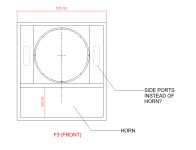
PS unsure if the drivers should be fully open on the front, or if they should have a band pass port like sysnergys?
Iv been wanting to build some mid/hi tops to go with my tham15's.
I used to have some martin philshaves and loved them. I cant deal with the complexity of synergy horns, so I thought Id attempt a "philshave minimal reduction", that would:
- be simple to build
- sit neatly on top of my tham15's.
- use lower cost drivers
- hopefully have some projection and imaging
- use one sheet of plywood for a pair.
- not have to custom build phase plugs or custom throat adapter.
I dont know anything about hornresp, so the iterations attached below may be nonsense. But Im hoping for any feedback, comments, guidance on moving this design to a good sounding and simple build.
PS unsure if the drivers should be fully open on the front, or if they should have a band pass port like sysnergys?
Attachments

What you are proposing still is a synergy horn. The Martin MH-212 is a midrange only (200 - 2,000 Hz) horn and cannot be used as a basis for a full range speaker.
How about a 12" direct radiator with a separate high frequency horn?
How about a 12" direct radiator with a separate high frequency horn?
Is this for home use levels or commercial? If for home, I’d say use direct radiators…….an 12” pro mid capped with a 1” CD and a modest, shallow lens for wide dispersion and imaging in a home setting. I believe the Tham is only good up to 150hz…..there’s a huge dip and then a large spike. Maybe a 10” mid can play down that low?…..depends on how loud you’re getting. A 12 would certainly give you some more midbass slam
Last edited:
From what I see in your images, it looks like you have a compression driver for the tweeter section at the apex of your midrange geometry. If that's the case, you may have a lot of Z distance to compensate for in your design as drawn (depending on midrange size). Part of the "port" function in the synergy horns is making the mid behave more like a point source nearer the tweeter. Without that, the distance between midrange and tweeter tends to be significant compared to the wavelength where crossover normally occurs.
You may have constructive/destructive interference just from the geometry of the horn and the midranges as drawn also, but I'm speculating on that point.
A Danley patent
https://patents.google.com/patent/US6411718B1/en
Discussion of spacing/wavelength
If you can do acoustic measurements and you have the drivers lying around, doing a quick prototype to check basic performance may be worthwhile. Emphasis on the "quick." Thrown together with the fastest method is the right approach to some prototypes.
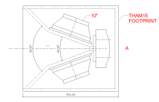
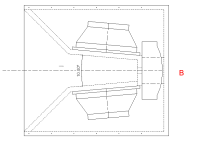
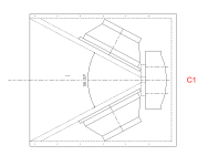
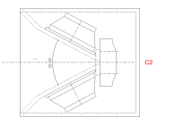
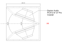
The Martin MH-212 "Phillishave" is a 90 x40 degree radial exponential horn, which has more gain down to around 250Hz, and wider dispersion than the parabolic expansions you have depicted in B, C & D. The MH-212 upper response is usable to 1500Hz due to the throat construction.I cant deal with the complexity of synergy horns, so I thought Id attempt a "philshave minimal reduction"...
"A" would have the most gain of the four, but usable upper response would be limited to ~400Hz, while the horn would provide no loading for the HF driver down that low.
A, B, C & D as drawn would severely mess up the frequency response of the both the mid and HF drivers, and provide almost no horn gain at 125Hz, the highest you'd likely want to cross the Tham 15".
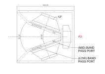
If you plan to share the same horn for both mid and high drivers, the band pass port will be better for both mid and HF drivers.I dont know anything about hornresp, so the iterations attached below may be nonsense. But Im hoping for any feedback, comments, guidance on moving this design to a good sounding and simple build.
PS unsure if the drivers should be fully open on the front, or if they should have a band pass port like sysnergys?
With 10", a MEH (multiple entry horn) acoustic crossover around 800 Hz is possible using cone filler plugs, without ~600Hz max.
If you want the HF driver to "keep up" to the 2x10" low mid, a 3" diaphragm will be required on a conical MEH, or 4" with no filler plugs.
You can use lower cost 10" drivers, but the lower crossover point raises the HF driver cost.
Art

To fill in some blanks: The system is usually used out doors for community disco/house/roller skate, So its more of a commercial sounding situation, and I dont know if a front radiating setup would have that image throw to keep up with the THAMs?
However mayhem13 Suggested a a front radiating design with a shallow lens, Im not quite sure what that would look like, any examples of this?
Its sounding like the consensus is that there needs to be a minimum of 12" drivers to meet the thams cross over limit.
I guess im ending up designing a "poor mans synergy horn" more then the philshave.
I will put together some more iterations based on feedback to see if anything starts to take shape.
PS understanding that there is a separate HF driver location, why does the Low driver setup work on this tannoy vq ? Is there some other trickery going on? It would be easy to build something like this then add a pre-manufactured HF waveguide.
PSS how do identify the 1/4" wave of a given speaker per the Danley video posted above? Is it related to the crossover points?
Last edited:

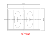
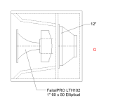
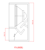
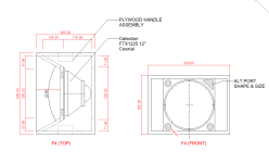
OK folks, here are more rand-o designs, please let me know if any of them have any value in exploring further, and would work well with the THAMS.
Attachments
You have a lot of inherently different things in those images. Several will be hard to just guess at. If you want to do a multi-entry horn, modeling and then prototyping is the best way to get somewhere useful. And probably mostly copying what someone else has already done, so you don't go down a lot of blind alleys. With a complicated design, there are more ways to do things wrong.
Here are a few threads on the topic, in case you haven't run across them yet. Many are specific to use cases different than yours, but the basics should still apply.
You may also want to start a new thread with that name in the title so more of the people that have built them are likely to chime in. Or tag some of them and see if they'll join this conversation.
https://www.diyaudio.com/community/...oject-based-on-sb-acoustics-h280-horn.414030/
https://www.diyaudio.com/community/threads/please-critique-my-multi-entry-horn-simulation.332137/
https://www.diyaudio.com/community/threads/synergy-horn-and-general-questions.387103/
https://www.diyaudio.com/community/threads/synergy-horn-questions.407369/
And ultimately, a simple coaxial arrangement is the most straightforward thing you've proposed. You can easily find precise build instructions for many of those, and some from manufacturers themselves. If it gives you enough output, it's a far simpler solution.
Last edited:
Thanks for bringing me back to reality. I should have titled the thread, "brain storm designs from an amateur"
The good news is that after after churning out all of these random drawings, and everyones feedback, I think I agree with you that coax will be the cheapest and simplest to get a fully formed image experience.
Iv never used coax before. I understand the concept that they align everything into a nice coherent wavefront, But do they naturally create that kind of "directed" long throw field like a synergy? Or could they benefit from some additional wave guides to focus the energy?
Any recommendations to start looking at for commercial coax projects that get down to 100Hz?
Also to complicate things: Would there be any benefit to try to capturing the back of speaker phase and try to horn it out to a front port(s)? Kind of a coax tapped horn.. from what iv read tapped horns dont sound to good when they get smaller..or even just a simple slot port?
Honestly if was a simple synergy/unity style horn that used only 2 drivers and 1 CD and no x-over, I dont think I could resist.
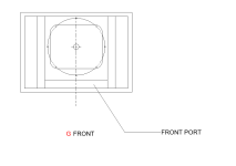
The last of my rambling drawings attached below. (coax focused)
The good news is that after after churning out all of these random drawings, and everyones feedback, I think I agree with you that coax will be the cheapest and simplest to get a fully formed image experience.
Iv never used coax before. I understand the concept that they align everything into a nice coherent wavefront, But do they naturally create that kind of "directed" long throw field like a synergy? Or could they benefit from some additional wave guides to focus the energy?
Any recommendations to start looking at for commercial coax projects that get down to 100Hz?
Also to complicate things: Would there be any benefit to try to capturing the back of speaker phase and try to horn it out to a front port(s)? Kind of a coax tapped horn.. from what iv read tapped horns dont sound to good when they get smaller..or even just a simple slot port?
Honestly if was a simple synergy/unity style horn that used only 2 drivers and 1 CD and no x-over, I dont think I could resist.
The last of my rambling drawings attached below. (coax focused)
Attachments
A 12" co-ax could easily "keep up" with the Thams with the usual disco bass "haystack" of +10dB or more <125Hz.To fill in some blanks: The system is usually used out doors for community disco/house/roller skate, So its more of a commercial sounding situation, and I dont know if a front radiating setup would have that image throw to keep up with the THAMs?
"Throw" is determined by SPL. SPL drops at -6dB per doubling of distance.
A more narrow high frequency dispersion pattern will provide more on-axis sensitivity, generally the difference between 90 and 60 degrees is ~+3dB using the same driver.
If you are covering a relatively wide area, 90degrees is the usual choice for a single cabinet per side.
Depends on the drivers, their configuration (sealed, bass reflex, front loaded horn, ported horn, etc.) and the Xmax of the drivers used.Its sounding like the consensus is that there needs to be a minimum of 12" drivers to meet the thams cross over limit.
Being cash poor does not mean you have to use poor designs 😉I guess im ending up designing a "poor mans synergy horn" more then the philshave.
No trickery, just a rather expensive co-ax mid high driver crossed ~550Hz to the "V" mounted woofers.PS understanding that there is a separate HF driver location, why does the Low driver setup work on this tannoy vq ? Is there some other trickery going on? It would be easy to build something like this then add a pre-manufactured HF waveguide.
The pass band electrical transfer function is the inverse of the acoustical response, the sealed "V" loaded woofers roll off ~-10dB between 550Hz and 125Hz.
One wants the drivers to be within 1/4 wavelength (360/90 degrees of phase difference) at the crossover frequency, or off axis cancellation (comb filtering) will occur. Phase response within 90degrees sums to +3dB, perfect alignment (0 degrees) sums to +6dB.PSS how do identify the 1/4" wave of a given speaker per the Danley video posted above? Is it related to the crossover points?
Sound travels ~1130 feet per second.
Speed of sound/frequency=wavelength.
Wavelength/4= one quarter wavelength.
1130Feet/550Hz=2' (24")
24"/4=6".
The VQ 100 vertical spacing is more than 1/4 wavelength, which would cause some lobing and comb filtering below and above the on axis plane in the frequency range of the acoustic crossover.
At any rate, a decent 12" or 15" co-ax on a stick would work OK for your out door community disco/house/roller skate system.
You definitely should put the mid-high above head level, which requires a lot more robust rigging solutions when the cabinets are heavy and present high wind loads.
Art
No, but you have to look at the tradeoffs to get that. However you slice it, it's typically going to be a pretty large speaker to get narrowed directivity into the low midrange. Whether it's synergy, a more typical multi-driver array, etc., they tend to get big."directed" long throw field like a synergy
On the lower end of the price scale are the Eminence Beta co-ax's.Any recommendations to start looking at for commercial coax projects that get down to 100Hz?
https://www.parts-express.com/Eminence-Beta-12CX-12-Coaxial-Driver-290-504?quantity=1
https://www.parts-express.com/pedocs/more-info/290-504--eminence-beta-12cx-cabinet-design.pdf
https://eminence.com/blogs/blog/great-uses-for-coaxial-products
Build document mentioned above. Includes a just legible schematic for the crossover. It's probably online somewhere also or a request to Eminence might get you a cleaner copy. The enclosure shape can be changed to whatever suits you as long as the volume is maintained.
https://cdn.shopify.com/s/files/1/0270/8665/1462/files/Eminence_DIY_StageMonitor.pdf?v=1613789489
Of course there are more expensive options out there, neodymium versions if you want something lighter, etc. But the Beta's will get you into the approach at a pretty reasonable price point.
Last edited:
Thank you for the education Art! Im starting to understand how the synergy has solved a lot of problems (and coaxial to some degree).
Can you recommend any coaxial designs that have a 60d or 90d wave guide to try to squeeze out another +3db ? Most that Iv come across are manufacture recommended ported boxs.
If I cant seem to find anything I guess Ill have to take a change and build the design above (minus the horn part) . Just not sure how to do the calc to make sure it will reach down to 100Hz in some meaningful way. I dont know how the iron law works, but the box feels to small to get to 100Hz flatish.
mattstat : Thank you for the referrals! volume was next on my list, so those designs will at least tell me Im in the ball park.horn design seems a little out of my pay grade at this point. But Im wondering if a scoop style opening at the bottom with one angled baffle with a +-160x500 mouth or (2) "port slots" on either side of the driver facing front,
would help me get to 100Hz and add some throw, or if it will just add complexity and literally blow out the coax image and just loose volume to baffles? I dislike the way bass reflex sounds and worry that the port approach will put me in that category.
Anything relying on actual horn behavior is more complex than an average person can do seat of their pants with a high likelihood of success, unless they're copying someone else's design precisely. Most rely on software to model the effects now. Without software, you need to understand quite a few details to get them right, and they typically won't be as compact as some of the newer approaches.
Typical ports only enhance output over a limited range, and not by a lot. If you don't need the few extra dBs, I'd skip it. But my natural tendency is to start things as simply as possible, then add complexity as needed. Though I'm also OK with doing a test box, then building a real one after that proves the point.
Whether the box is ported or sealed, the radiation pattern should be the same. A poorly designed ported enclosure can certainly sound bad, but if you follow an established design it should be OK. It is more important to properly high-pass a ported enclosure, since excursion gets extreme below the port tuning frequency. A normal sealed enclosure inherently limits excursion at low frequencies, so they are a little more forgiving.
Last edited:
The DSL SM-80 (80x80 degree dispersion) is an example of a sealed co-ax design using the B&C12CXN76 which has a short conical horn which adds over 3dB in the range above ~180Hz, but no gain at 100Hz.Can you recommend any coaxial designs that have a 60d or 90d wave guide to try to squeeze out another +3db ? Most that Iv come across are manufacture recommended ported boxs.
Small and light enough for easy pole mounting.
It's convenience has made it a popular cabinet for the "weekend warriors" that don't want or need the larger Synergy horns.
Using the B&C 12CXN88 (an upgrade over the 2CXN76) in a similar size cabinet without the short horn and the B&C passive crossover could provide slightly more output due to it's increased Xmax, though it is ~-2dB less sensitive at 100Hz.
126dB without exceeding Xvar at 125Hz, plenty for a pair of 15" Thams.
No horn in the size you are looking at has much directionality in the 100Hz range, so they don't "add some throw", though may add some sensitivity if folded.horn design seems a little out of my pay grade at this point. But Im wondering if a scoop style opening at the bottom with one angled baffle with a +-160x500 mouth or (2) "port slots" on either side of the driver facing front, would help me get to 100Hz and add some throw, or if it will just add complexity and literally blow out the coax image and just loose volume to baffles?
A "scoop" (back loaded horn) would probably have a large cancellation in the crossover region, negating any advantage over a simple sealed cabinet.
An angled baffle would ruin the coax image and response.
With bass reflex ports, the coax response could easily be made flat to well below 100Hz, you could use it without subs if you wanted. Easy to make port "bungs" to seal them if the extra +3 to 6dB they add (for free..)isn't required.
Art
Thant's what Im talking about ..Free +3db and potentially full range!With bass reflex ports, the coax response could easily be made flat to well below 100Hz, you could use it without subs if you wanted. Easy to make port "bungs" to seal them if the extra +3 to 6dB they add (for free..)isn't required.
Would I need to use PVC or can they be open hole ports?
Im getting kind of excited now because this project is:
- Meeting Mid/low budget
- meeting the simplicity / minimalist factor
- CNC machine efficiency and minimal tool change outs.
- might have a little throw and directivity
- will flush stack on top of thams for a nice look.
- minimal size for car style roadies
- has a chance of meeting my thams x-over
- hopeful chance of good phase response
- can maybe use as full range alone
- one down size is will be difficlt to locate a tophad for a pole mount. but could be really cool stacked due to the 45d top and bottom throat.
Also would the ports join the directivity party?
Attachments
You can use cardboard, wood or PVC for ports.Would I need to use PVC or can they be open hole ports?
If you mean by "open hole ports", a port the depth of the plywood, for a given Fb, they will have too little volume and will be "blown out" at higher drive levels.
Top hats are readily available.
- one down size is will be difficlt to locate a tophad for a pole mount.
The bass reflex port/driver phase relationship is a complicated subject, but suffice it to say the phase "alignment" is mostly determined by the Fb, the box tuning frequency.The last question before I go down the volume road is: Would the ports as shown in the updated drawing below, help to keep phase response aligned? or would they be better suited if located in the front baffle panels?
Also would the ports join the directivity party?
The Fb should be well below the crossover frequency to the subwoofer.
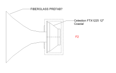
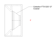
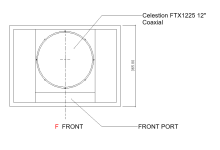
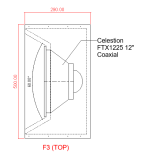
A Fb similar to the the driver's Fs (free air resonance) is typical, the Fs of the Celestion FTX1225 is 47.8Hz.
The port output is omnidirectional, it has no low frequency directivity.
An Fb above Fs can help fill in the response dip below the short horn's output boost, but may result in the peaky, muddy response that you probably don't like..
The FTX1225 has only 4mm Xmax, less than half of the B&C 12CXN88.
The 12CXN88 could put out ~6dB more clean low frequency in a sealed enclosure, or at frequencies ~1/3 octave above Fb.
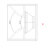
As drawn, your parabolic side horn angles and flat top and bottom will severely eff up (ruin) the response above ~300 Hz.
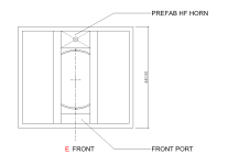
If you want response similar to the SM-80 and don't want to make a round horn, you could do a scaled up version of what Frazier did with the 8" loudspeaker CAT 40 (50Hz Fb):
The horn angles should be equal or greater than the nominal dispersion of the co-ax you decide to use, 80 rather than 60 degrees.
Since the short conical horn only increases output above around 200Hz and has no directivity control below that, the cabinet will require more EQ than a front mounted speaker for something resembling flat response.
Art
Last edited:
OK. I may have to go Syntrip..LOL
They are checking all the boxs, I just need to put in some more work to get organized. For some reason I I remembered them as being more complicated 3 ways.
Im sure it goes without saying but thank you for your help and education Art, and that you for the really nice community released design!
Have there been any updates bat rev 4? I know you weren't to happy with the port performance.
How much DSP/EQ is happening to get that response?
- Home
- Loudspeakers
- Multi-Way
- Mid/Hi design reduction inspired by Martin Philshave