After lurking dozens of years here on diyaudio , I decided to build my own riaa tube preamps.
After retirement I recently picked up an old hobby, tubes and amps, combined with a renewed interest in playing vinyl , I acquired some pcb's on aliexpress. One board was based on the Mofi riaa mm/mc preamp, two dual opamps opa1652, two voltage regulators for symmetric psu ,+18V and -18V, and the split active low boost - passive high roll-off riaa network, ready in no time, and sounded quite nice, no hum, noise or other inconveniences, but not very satisfying to listen to.
After some reading on the internet, I got interested in some tube based riaa preamps, in particular the ear384 which seems a shunt feedback design, the Joe Tritschler split passive high - shunt fb active low boost design with unobtainable tubes , and the JL Hood , originally solid state but translated to tubes-mosfet hybrid by me, split series feedback low boost and shunt fb high roll-off design. To that end I acquired two pcb's from aliexpress, one designed for the ear384 design and one for the shure M65 preamp. I wasn't very impressed with the sound of the Mofi ear384, it seemed to have more than twice the voltage output at 20kHz than at 20Hz. Measured with an inverse riaa filter , modelled after the design on Rod Elliot's webpages, with the 1k gain setting resistor altered to 590R , much closer to the original 604R from this design, with all inverse riaa components selected to be within 0.1% of the target values, this fed by a GFG-8015 function generator. So I changed that to the tube-mosfet hybrid JL Hood design:

A few errors , the 43R from the shunt feedback network is connected after the 3.3uF capacitor and the 590R isn't there.
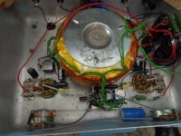
This was a lot better to my ears. Allso measurements with the inverse riaa filter seemed to indicate a much better riaa conformance , with deviations <0.2dB , and a slight roll of at 20kHz, depending on the actual value of the 81.5pF capacitor. The CCS loading the ecc83 is made out of a J112 jfet and a cpc3960 depletion mode mosfet with ca 1mA current. The active low boost riaa feedback network is targeted at around 4mA current. The capacitor parallel to the source resistor can be made into a rudimentary rumble filter. The 6J52P pentode can be anything , ef184 e280f e180f e186f e810f or 6j11p. This my not very tidy test model:

Two gas discharge tubes for ca. 289V stabilized HT and a LM317 for a stabilized 12.6V , the two 6J52P tubes here used run heaters in series, just like the single ecc83. Riaa componenets are selected to match between left and right channel. Because of the feedback design tube matching on gain is less relevant and left and rigt outputs match very nicely.
I allso read much regard for a completely passive design, so I used the shure M65 board to make a complete passive design:

Again a hybrid design , with a 2sk117 jfet cascading into a 6BK7A triode , here cascoding the jfet and the triode would give higher gain, but I wanted to have a line level output voltage. Output is buffered by the ccs loaded mosfet source follower, whereafter the passive riaa network, the values shown gave me the best riaa conformance, though official calculations give sligtly different values. The second triode is ccs loaded with the "mu?" output used as the output. The 825R for the cathode, unbypassed, is to limit output voltage , a LM385Z-adj. would yield more gain, but I wanted to keep the output at approx. line level. This amp allso sounded very nice , though somewhat softer in tone , but absolute no listening fatigue, so much so I have to reconsider playing records because the cost of good needles is pretty inflating my household budget. This is the modified shur M65 pcb:

I couldn't decide which was the better of the above two designs, or the solid state mofi design. I find the tube designs more interesting to listen to, I think mainly because of the looks, with solid state there ain't much to look at, and , despite what people might say, looks count for the listening experience.
To listen to the tube riaa preamps , I allso decided to build an integrated power tube amp, consisting of the standard PP power amp, a tube based tone control, and a builtin riaa preamp.

It's based om el86/6p43p tubes , with a 6BK7A based LTP phase splitter ,ccs in the tail to the -50V ,and a shared ecc83 input tube for L and R channels. The tone control is based on the ecc832 , the AU halve is used as the CF input with the AX halve serving as the actual tone control triode, baxandall type, so no gain in mid position. Both loaded with ccs's made of a J112 and a CPC3960, 4mA for the AU and 1.2mA for the AX , wherev the "mu" output is used for connecting to the power amp input. The riaa preamp is based on the Joe Tritschler passive -active shunt fb design, but with ecc83 tubes, a 2sk208 cascading into the the ecc83 as input, that is ccs loaded with 1.2mA , with the mu output loaded with the passive riaa high roll-of. It's cathode held at fixed voltage by two LM385Z-5 vref's that need only 10 micro A to work properly, and with 1Ohm dynamic resitance no capacitor for AC is needed. The second triode halve , allso ccs loaded with 1.2mA functions as the low boost shunt feedback amp and output to the volume pot. This riaa preamp allso sounds very good, albeit not as "clean" as the other two. The whole amp is fed by a smps , supposedly 300Watt, I got cheap from aliexpress. It's advertised to deliver 300V/600mA, 12.6V/?A , 6.3V/?A and -50V/100mA . Actual output voltages weren't that good. The 6.3V has it's own switcher to make the 6.3V from the 12.6V output. It gave under load only 5.9V and I had to change the feedback resistor value to the switcher to a slightly higher value, it's now 6.23V which seems close enough. The 12.6V was only 12.18V, after allso changing the feedback resitor to the calculated necessary value I got 12.54V , close enough, which allso brought the HT output from 278V to 283V, still quite some lower than the advertised 300V , but since I was using el86 tubes in standerd UL PP design, it was more than enough. Loaded with 5k OPT's , it delivers 18Watts per channel , constant tone test.
The amplifier has no appreciable hum or noise when line level inputs are selected and volume max with ear against speaker cone, but considerable hum when one of the riaa preamps is selected. The seperate riaa preamps have transformer psu's and sound more open than the built-in riaa preamp, but all have equal loud hum with volume at max. Might the smps be the reason for the less open sounding built-in riaa preamp ? I do see a lot of HF dirt on the several supply lines, in the 100kHz till 1MHz range. After changing the power supply input capacitor from the low quality 150uF 400V type to a brand quality 390uF 450V it was less, but still. From scope readings it seems to operate around the 115kHz region and is of the LLC resonant type. The output supply lines have no inductors , like you see in computer psu's. What would be usable types for this frequency and application? The tone control and power amp don't seem to suffer that much from the smps, but I have the idea the riaa preamp has. The tone control and riaa tubes are HT fed by a voltage regulator that brings down the 283V HT to 253V. I tried shielding the smps but that didn't had much effect. Allso, a signicant 50Hz ripple is present on the supply lines , as I understood from reading several papers, caused by the capacitor between the groundplanes of the power input and the supply output. Is there a preferred way of grounding this contraption. I now have a earthed power entry with HF filter to supress HF bleeding into the powerlines and at the supply side a bus ground connected to the power earth entry. Power ground is o.c. not connected. to any of earth or supply ground , except for the capacitor between the power ground and supply ground, which is there for safety reasons as I could make up of reading of the appropriate papers.
And the hum, how could I get most of the hum removed, when I connect the record player through the mofi solid state preamp, no hum at all, when I use one of the 3 tube riaa preamps lots of hum. I have to say that at the normal listening levels of the volume knob , there is no hum noticeable in listening position, only a bit with ear against speaker.
In the end I would say that all riaa preamps, when built to standards sound the same, with the fully active a bit more snappy and the fully passive a bit more airy , and the in-betweens , well , in between. The solid state preamp has no hum or noise issues whatsover, but is uninspiring and a bit flat sounding, probably mainly it doesn't look that good. The tube based riaa preamp are hummy at max volume, couldn't figure out where that comes from, grounding is exactly the same as with the solid state preamp. Noise is allso not a preblem for the tube preamps, though the smps fed riaa preamp seems to suffer a bit in cleanliness, hard to tell. I will at one point replace the smps with a transformer based psu, see how that goes. I am not sure if I hear that right, but smps seems to compress the audio a bit, but than again, might be completely subjective, knowing what you listen to might make you hear things that aren't there. Anyways, all the riaa preamps seem to perform quite well. The mofi ear384 and the shure M65 , the original designs for two of the pcb's I had bought sounded dreadful and very fatiguing, not recommended. I think I like the fully passive design best for acoustic/classical music and the JL Hood active series - active shunt design best for the electrified classic blues, blues-rock etc. music I like to listen to. Any comments on the designs would be appreciated. I am no electronics engineer so there might be a lot to comment on, all designs are cobbled together from bits and pieces I found lurking throught diyudio and the internet in general.
Thanks for reading this travel log into tubesland.
Systux
After retirement I recently picked up an old hobby, tubes and amps, combined with a renewed interest in playing vinyl , I acquired some pcb's on aliexpress. One board was based on the Mofi riaa mm/mc preamp, two dual opamps opa1652, two voltage regulators for symmetric psu ,+18V and -18V, and the split active low boost - passive high roll-off riaa network, ready in no time, and sounded quite nice, no hum, noise or other inconveniences, but not very satisfying to listen to.
After some reading on the internet, I got interested in some tube based riaa preamps, in particular the ear384 which seems a shunt feedback design, the Joe Tritschler split passive high - shunt fb active low boost design with unobtainable tubes , and the JL Hood , originally solid state but translated to tubes-mosfet hybrid by me, split series feedback low boost and shunt fb high roll-off design. To that end I acquired two pcb's from aliexpress, one designed for the ear384 design and one for the shure M65 preamp. I wasn't very impressed with the sound of the Mofi ear384, it seemed to have more than twice the voltage output at 20kHz than at 20Hz. Measured with an inverse riaa filter , modelled after the design on Rod Elliot's webpages, with the 1k gain setting resistor altered to 590R , much closer to the original 604R from this design, with all inverse riaa components selected to be within 0.1% of the target values, this fed by a GFG-8015 function generator. So I changed that to the tube-mosfet hybrid JL Hood design:
A few errors , the 43R from the shunt feedback network is connected after the 3.3uF capacitor and the 590R isn't there.
This was a lot better to my ears. Allso measurements with the inverse riaa filter seemed to indicate a much better riaa conformance , with deviations <0.2dB , and a slight roll of at 20kHz, depending on the actual value of the 81.5pF capacitor. The CCS loading the ecc83 is made out of a J112 jfet and a cpc3960 depletion mode mosfet with ca 1mA current. The active low boost riaa feedback network is targeted at around 4mA current. The capacitor parallel to the source resistor can be made into a rudimentary rumble filter. The 6J52P pentode can be anything , ef184 e280f e180f e186f e810f or 6j11p. This my not very tidy test model:
Two gas discharge tubes for ca. 289V stabilized HT and a LM317 for a stabilized 12.6V , the two 6J52P tubes here used run heaters in series, just like the single ecc83. Riaa componenets are selected to match between left and right channel. Because of the feedback design tube matching on gain is less relevant and left and rigt outputs match very nicely.
I allso read much regard for a completely passive design, so I used the shure M65 board to make a complete passive design:
Again a hybrid design , with a 2sk117 jfet cascading into a 6BK7A triode , here cascoding the jfet and the triode would give higher gain, but I wanted to have a line level output voltage. Output is buffered by the ccs loaded mosfet source follower, whereafter the passive riaa network, the values shown gave me the best riaa conformance, though official calculations give sligtly different values. The second triode is ccs loaded with the "mu?" output used as the output. The 825R for the cathode, unbypassed, is to limit output voltage , a LM385Z-adj. would yield more gain, but I wanted to keep the output at approx. line level. This amp allso sounded very nice , though somewhat softer in tone , but absolute no listening fatigue, so much so I have to reconsider playing records because the cost of good needles is pretty inflating my household budget. This is the modified shur M65 pcb:
I couldn't decide which was the better of the above two designs, or the solid state mofi design. I find the tube designs more interesting to listen to, I think mainly because of the looks, with solid state there ain't much to look at, and , despite what people might say, looks count for the listening experience.
To listen to the tube riaa preamps , I allso decided to build an integrated power tube amp, consisting of the standard PP power amp, a tube based tone control, and a builtin riaa preamp.
It's based om el86/6p43p tubes , with a 6BK7A based LTP phase splitter ,ccs in the tail to the -50V ,and a shared ecc83 input tube for L and R channels. The tone control is based on the ecc832 , the AU halve is used as the CF input with the AX halve serving as the actual tone control triode, baxandall type, so no gain in mid position. Both loaded with ccs's made of a J112 and a CPC3960, 4mA for the AU and 1.2mA for the AX , wherev the "mu" output is used for connecting to the power amp input. The riaa preamp is based on the Joe Tritschler passive -active shunt fb design, but with ecc83 tubes, a 2sk208 cascading into the the ecc83 as input, that is ccs loaded with 1.2mA , with the mu output loaded with the passive riaa high roll-of. It's cathode held at fixed voltage by two LM385Z-5 vref's that need only 10 micro A to work properly, and with 1Ohm dynamic resitance no capacitor for AC is needed. The second triode halve , allso ccs loaded with 1.2mA functions as the low boost shunt feedback amp and output to the volume pot. This riaa preamp allso sounds very good, albeit not as "clean" as the other two. The whole amp is fed by a smps , supposedly 300Watt, I got cheap from aliexpress. It's advertised to deliver 300V/600mA, 12.6V/?A , 6.3V/?A and -50V/100mA . Actual output voltages weren't that good. The 6.3V has it's own switcher to make the 6.3V from the 12.6V output. It gave under load only 5.9V and I had to change the feedback resistor value to the switcher to a slightly higher value, it's now 6.23V which seems close enough. The 12.6V was only 12.18V, after allso changing the feedback resitor to the calculated necessary value I got 12.54V , close enough, which allso brought the HT output from 278V to 283V, still quite some lower than the advertised 300V , but since I was using el86 tubes in standerd UL PP design, it was more than enough. Loaded with 5k OPT's , it delivers 18Watts per channel , constant tone test.
The amplifier has no appreciable hum or noise when line level inputs are selected and volume max with ear against speaker cone, but considerable hum when one of the riaa preamps is selected. The seperate riaa preamps have transformer psu's and sound more open than the built-in riaa preamp, but all have equal loud hum with volume at max. Might the smps be the reason for the less open sounding built-in riaa preamp ? I do see a lot of HF dirt on the several supply lines, in the 100kHz till 1MHz range. After changing the power supply input capacitor from the low quality 150uF 400V type to a brand quality 390uF 450V it was less, but still. From scope readings it seems to operate around the 115kHz region and is of the LLC resonant type. The output supply lines have no inductors , like you see in computer psu's. What would be usable types for this frequency and application? The tone control and power amp don't seem to suffer that much from the smps, but I have the idea the riaa preamp has. The tone control and riaa tubes are HT fed by a voltage regulator that brings down the 283V HT to 253V. I tried shielding the smps but that didn't had much effect. Allso, a signicant 50Hz ripple is present on the supply lines , as I understood from reading several papers, caused by the capacitor between the groundplanes of the power input and the supply output. Is there a preferred way of grounding this contraption. I now have a earthed power entry with HF filter to supress HF bleeding into the powerlines and at the supply side a bus ground connected to the power earth entry. Power ground is o.c. not connected. to any of earth or supply ground , except for the capacitor between the power ground and supply ground, which is there for safety reasons as I could make up of reading of the appropriate papers.
And the hum, how could I get most of the hum removed, when I connect the record player through the mofi solid state preamp, no hum at all, when I use one of the 3 tube riaa preamps lots of hum. I have to say that at the normal listening levels of the volume knob , there is no hum noticeable in listening position, only a bit with ear against speaker.
In the end I would say that all riaa preamps, when built to standards sound the same, with the fully active a bit more snappy and the fully passive a bit more airy , and the in-betweens , well , in between. The solid state preamp has no hum or noise issues whatsover, but is uninspiring and a bit flat sounding, probably mainly it doesn't look that good. The tube based riaa preamp are hummy at max volume, couldn't figure out where that comes from, grounding is exactly the same as with the solid state preamp. Noise is allso not a preblem for the tube preamps, though the smps fed riaa preamp seems to suffer a bit in cleanliness, hard to tell. I will at one point replace the smps with a transformer based psu, see how that goes. I am not sure if I hear that right, but smps seems to compress the audio a bit, but than again, might be completely subjective, knowing what you listen to might make you hear things that aren't there. Anyways, all the riaa preamps seem to perform quite well. The mofi ear384 and the shure M65 , the original designs for two of the pcb's I had bought sounded dreadful and very fatiguing, not recommended. I think I like the fully passive design best for acoustic/classical music and the JL Hood active series - active shunt design best for the electrified classic blues, blues-rock etc. music I like to listen to. Any comments on the designs would be appreciated. I am no electronics engineer so there might be a lot to comment on, all designs are cobbled together from bits and pieces I found lurking throught diyudio and the internet in general.
Thanks for reading this travel log into tubesland.
Systux
Last edited:

Sorry, didn't read all of your post. Re hum, it sounds like a mains earth loop. I had a similar thing a few weeks back. I've got an extension lead, plugged into my living room double wall socket. There's another extension lead plugged into that, so, two extension leads daisy chained to get enough plug sockets.
Valve amp is plugged into one extn lead, PC into the other, result, loud hum & noise. If I plug another amp into extn lead two, noise goes away. There's a two way speaker patch bay too to complicate things further, but hopefully you get the gist.
So, try mucking about with your mains setup if using extn leads or lift the earth on the duff preamp, then earth it through your power amp. See here for more info - http://www.valvewizard.co.uk/Grounding.html
Andy.
In my RIAA preamplifiers, the stray field of mains transformers was always the cause of hum that was the hardest to get under control, unless the preamplifier could be placed at a large distance from all mains transformers - external power supply, not stacking the preamplifier on top of some other equipment with a mains transformer. It helps to keep the loop area from the input connector to the input device via the feedback network (if there is series feedback at the input) back to the ground side of the input connector small, but even then...
You like micropower bandgap references/shunt regulators such as the LM385, but they have the disadvantage that they are quite noisy. Fortunately you don't use them in the first stage.
In KiCad, you can change the value field of the components. I think you have to right-click on the text "R" or "Csmall" to fill in a value, but maybe I'm mistaken and you have to double-click.
The effect of AC coupling on the first pole of passive RIAA correction is often neglected, but that's often not correct. When the filter capacitors are small, which they are not in your case, the highest pole can sometimes be affected substantially by Miller effect in the next stage.
@Andy , thanks for your insights. I tested the amps today again , no signal and volume pot at max output, a level which would normally send the power amp in considerable clipping because the riaa preamps put out around 700 mV while the sensitivity of the power amp is 400mV for max output level. No hum was noticeable other than the slight hiss caused by the smps when line inputs or the solid state riaa preamp was selected. The builtin riaa circuit produced a louder whine compared to the line inputs , resembling the soft whine you can sometimes hear coming from the HF transformer in a smps. The two external riaa preamps gave a slight hum, audible without having to put my ear to the speaker cone, but no whine like the builtin riaa preamp and as stated , only at volume max , no hum was audible with the pot set to normal listening levels. It seems I didn't hear the loud hum, I only saw it on the scope , exactly for the reason you mentioned. The integrated tube amp has a netfilter entry with earth connection , just like the scope and the function generator I recently bought to give some body to my hobby. The scope produced heavy ground loop signals because both powerline earth and signal ground were connected between amp, scope and function generator. I never actually heard it , I only saw it. When I disconnected the scope probe ground wire , and the signal ground from the generator, the ground loop signals disappeared from the scope screen. The tube amp is the only audio component I have that has a powerline earth connection, mainly because it has a smps and needs a netfilter to stop HF entering the powerlines. I don't connect computer or other devices with a mains power earth connection to my tube amp, only a record player and a cd player, so no problems there.
@marcel , the JL Hood design preamp, with the yellow pcb, produces slightly more hum, than the passive preamp, with the black pcb. It has a EI transformer , while the other one has a toroidal transformer. Maybe that's what causing the audible hum at max volume. I always thought that toroids need less shielding because the core is completely covered with the windings, with no airgap at all. I have a toroid to replace the EI transformer , and measure again.
With regards to the band gap voltage references , I came to them because I read about led biasing the cathode, because of their low dynamic impedance need no bypass cap.
When trying to figure out the feedback circuit of the smps , I read some paper about LLC resonance smps with schematic overview. That resembled quite closely the smps here used, and it's output voltage was referenced via a TL431. Googling for the datasheet for the TL431 , results came up for the LM385 of TI , and reading that datasheet , it mentioned a dynamic impedance of only 1 Ohm , considerably less than a led, and the noise figure is 1-2 micro volt, which is comparable to a small signal triode. Travish Design has an index of noise measurements for various tubes, the ecc83 ranges from 0.6 to 2.3 microvolt , the ecc88 , only the very best selected , hoover around 0.6 microvolt too, the 2sk209 jfet has around 0.3 microvolt, the 2sk208 around 0.15.
What I wonder is, wouldn't the noise at the grid and the cathode cancel each other out? It's kind of a common mode signal , noise or is that thought wrongly ? Noise I hear is mainly produced by the stylus , scratching through the grooves, what makes me wonder, wouldn't the stylus tip get very hot by the friction between record and stylus, and couldn't that produce lasting deformations to the vinyl ? Would the use of something like the lencoclean fluid dispenser used in the heydays of record players, be actual very good to keep stylus tip temeperature at acceptable levels?
Thanks for the kicad pointers, I downloaded the programm a few days ago to make some readable schematics to include here on diyaudio, I used to use dia as a schematics editor, ages ago, but that programm doesn't contain valve symbols. Luckily there are now some better usable editors for linux too.
This is the schematic of the builtin riaa preamp, the split passive-active Joe Tritschler based design :

The HT voltage is 250 not 280 and the 1k resistor between first stage and second stage in the HT line isn't there , nor is the associated capacitor. The R3 680 Ohm is actually 825 Ohm and there is a 1M grid leak resistor from the connection point of the 147k, 49k and 1k resistor to ground The 2sk208 is a very low-noise low current and allso low gm jfet. I tried to maximize the gain of both stages, to have some shunt feedback overhead and still get the desired 800mV out at 4mV input. The values shown gave the flattest riaa output , within 0.3dB and , if I remember correctly , 800mV out at 4mV in. I was contemplating the use of a higher gm jfet at the input , with a combined triode-pentode tube like the 6KV8 , high-mu triode with a high gm pentode., running at much higher currents to have much more gain in the second stage , as to have proper feedback levels at around 20Hz. An other option would be to use a cascode with source-follower output buffer, with a high Gm jfet like the NSVJ3557 and use ecc81 instead of ecc83, but the downside there is that it becomes more of a solid state preamp than a tube preamp.
Systux.
@marcel , the JL Hood design preamp, with the yellow pcb, produces slightly more hum, than the passive preamp, with the black pcb. It has a EI transformer , while the other one has a toroidal transformer. Maybe that's what causing the audible hum at max volume. I always thought that toroids need less shielding because the core is completely covered with the windings, with no airgap at all. I have a toroid to replace the EI transformer , and measure again.
With regards to the band gap voltage references , I came to them because I read about led biasing the cathode, because of their low dynamic impedance need no bypass cap.
When trying to figure out the feedback circuit of the smps , I read some paper about LLC resonance smps with schematic overview. That resembled quite closely the smps here used, and it's output voltage was referenced via a TL431. Googling for the datasheet for the TL431 , results came up for the LM385 of TI , and reading that datasheet , it mentioned a dynamic impedance of only 1 Ohm , considerably less than a led, and the noise figure is 1-2 micro volt, which is comparable to a small signal triode. Travish Design has an index of noise measurements for various tubes, the ecc83 ranges from 0.6 to 2.3 microvolt , the ecc88 , only the very best selected , hoover around 0.6 microvolt too, the 2sk209 jfet has around 0.3 microvolt, the 2sk208 around 0.15.
What I wonder is, wouldn't the noise at the grid and the cathode cancel each other out? It's kind of a common mode signal , noise or is that thought wrongly ? Noise I hear is mainly produced by the stylus , scratching through the grooves, what makes me wonder, wouldn't the stylus tip get very hot by the friction between record and stylus, and couldn't that produce lasting deformations to the vinyl ? Would the use of something like the lencoclean fluid dispenser used in the heydays of record players, be actual very good to keep stylus tip temeperature at acceptable levels?
Thanks for the kicad pointers, I downloaded the programm a few days ago to make some readable schematics to include here on diyaudio, I used to use dia as a schematics editor, ages ago, but that programm doesn't contain valve symbols. Luckily there are now some better usable editors for linux too.
This is the schematic of the builtin riaa preamp, the split passive-active Joe Tritschler based design :
The HT voltage is 250 not 280 and the 1k resistor between first stage and second stage in the HT line isn't there , nor is the associated capacitor. The R3 680 Ohm is actually 825 Ohm and there is a 1M grid leak resistor from the connection point of the 147k, 49k and 1k resistor to ground The 2sk208 is a very low-noise low current and allso low gm jfet. I tried to maximize the gain of both stages, to have some shunt feedback overhead and still get the desired 800mV out at 4mV input. The values shown gave the flattest riaa output , within 0.3dB and , if I remember correctly , 800mV out at 4mV in. I was contemplating the use of a higher gm jfet at the input , with a combined triode-pentode tube like the 6KV8 , high-mu triode with a high gm pentode., running at much higher currents to have much more gain in the second stage , as to have proper feedback levels at around 20Hz. An other option would be to use a cascode with source-follower output buffer, with a high Gm jfet like the NSVJ3557 and use ecc81 instead of ecc83, but the downside there is that it becomes more of a solid state preamp than a tube preamp.
Systux.
According to https://www.ti.com/lit/ds/symlink/lm185-adj.pdf the noise of an LM385 is typically 50 uV from 10 Hz to 10 kHz when you set it to the lowest possible voltage, 1.24 V. It increases at higher settings, 170 uV at 5.3 V.
In the first circuit of post #1, this noise is essentially directly added to the noise of the valve of the second stage, but fortunately there is the gain of the first stage in front of it. In the circuit of post #4, the voltage gain of Q1 reduces the effect of the voltage reference noise.
In the first circuit of post #1, this noise is essentially directly added to the noise of the valve of the second stage, but fortunately there is the gain of the first stage in front of it. In the circuit of post #4, the voltage gain of Q1 reduces the effect of the voltage reference noise.
@marcel You are absolutely right, I missed that in the specsheet and looked at the graph of the noise which is in nV per sqrt of Hz, not in nV. They are 40-80 times more noisier than a led or a zener diode. Time to reconsider, on the other hand , they are so easy in use, with one simple 150k trimpot you can make stepless variable voltage reference from 1.2 till 5.3 V requiring only 10uA current. I have a collection of clear leds, but they all have the same voltage drop, 2V, no matter the emitted color, and capacitors are bulky and don't like heated environments.
The first circuit of post #1 gives besides the slight hum at max volume allso some sputtering noises , erratic but continuously , thought it was pentode noise, but it might as well be the voltage reference. I can get the 1.77V needed there as well by using a 1V zener and a 1n4148 diode, see if that helps, the leds I have settle at 2.1V at lower current than desired there. The other circuits where the voltage references are used give no audible noise at max volume as far as I can hear.
The first circuit of post #1 gives besides the slight hum at max volume allso some sputtering noises , erratic but continuously , thought it was pentode noise, but it might as well be the voltage reference. I can get the 1.77V needed there as well by using a 1V zener and a 1n4148 diode, see if that helps, the leds I have settle at 2.1V at lower current than desired there. The other circuits where the voltage references are used give no audible noise at max volume as far as I can hear.
The sputtering noises were due to the pentode type used, replaced them with 6J11P and the sputtering noises are gone. Trying to acquire some affordable e280f or e810f , but prices of those are insane. Still more hum at max volume than the other standalone riaa preamp, so embarking on replacing the EI transfomer for a toroidal one, and build it into some sort of shielded enclosure .
I've shielded noisy components with copper tape grounded in one of my preamp builds. Typically a toroid tfmr (non shielded) will kick out more EMF than an EI type tfmr. Try wrapping the tfmr in ali foil then ground it as an experiment.
Andy.
Andy.
@Andy, I've read here and there papers from toroid manufacturers and they are pretty adamant about toroids have significant lower emf and inductance leakage.
https://johnsoncoil.com/frequently-...e-advantages-of-using-a-toroidal-transformer/ e.g. Are you sure that toroidal trfmr's have higher emf leakage. I just replaced the EI trfmr in my technics sl-j1 linear tracking turntable to a small toroidal trfmr. Hear no difference by the way, but torroidals have significant lower losses , especially in the lower VA category, and as this turntable has an on-off switch only for the secondary not for the primary , so the trfmr is allways on, it seemed better to replace it.
About shielding, I understood that for frequency below 100kHz, mumetal and the likes shielding is necessary. I have a number of copper clad aluminum sheets, with an insulation layer in between, from a thrift store, probably used for led lightning or something. Anyways, that would be good material to build a trfmr housing from ?
Systux
You could be right about toroids having less EMF but I can confirm a copper band around a toroid does reduce 50hz hum, see pic of a SE 6V6 amp I built. The 6SL7 IP valve is right next to the mains toroid. Without band = hum, with band = no hum.
That sounds like a possible material, you can but try. As mentioned an old techs tip to find/reduce hum is to use an ali plate grounded with a jump lead moved about the amp & placed in between suspect components. Obviously you have to be careful not to touch any high voltage.
Andy.
That sounds like a possible material, you can but try. As mentioned an old techs tip to find/reduce hum is to use an ali plate grounded with a jump lead moved about the amp & placed in between suspect components. Obviously you have to be careful not to touch any high voltage.
Andy.
Attachments
@Andy , I remembered I had several copper sheets salvaged from old trafo's , I found one again and I wrapped it around the EI transfomer like this :

and grounded it to power earth. A bit amazed it actually worked , despite knowing it should work because that's why it's done with quality transformers. And yes, the induced hum was gone, only remained a slight hiss when volume max no record playing, so that was quite succesfull , thanks for pointing out it really works. I can't quite make out from you photograph how you wrapped the copper foil around the toroid. Simply wrap it around the outer edge ? I think with the toroid there's more going on. Used with the
passive riaa corection board , #2 in the first post, it gives a slight hum at max volume, no signal, but with the split feedback board, #1 in the first post, there's considerable hum at max volume ,no signal. I remember reading somewhere about that phenomenon, caused by the near perfect coupling between de windings or something like that, or maybe capacitive coupling between the windings , have to look it up again .
Anyways, I measured the gain of the first stage of above riaa board , and at 1kHz 4mV in, I get 48V out (more than 50V when not connected to the second stage). When frequency dependant feedback is connected I get 46mV out at 1kHz and ca 44mV at 20Hz and 440mV at 20kHz. That means I have 60dB feedback at 1kHz and 20kHz and 40 at 20Hz. I hope this is linearizing the mosfet enough. I chnaged the source follower mosfet at the output from a STU1HN60K3 to a BSP135. As I understood from reading the output impedance is 1/Gm , but Gm is nearing zero for the STU1HN60K3 and for the BSP135 it's actually defined at low currents, being a low current device itself.

From the graph I understand that it's still something like 20-25mS , resulting in a 400-500 Ohm Zout. Is that about right ? For other mosfets , when a Gfs is published at all , that becomes blurry at currents below 100mA, let alone at 5mA.
Up to investigating the BestPentode circuit, as @bondini ( https://www.diyaudio.com/community/...vite-micro-with-a-pentode-first-stage.293672/ ) pointed out to me as a solution for possible flicker noise. I think the 6J52P had a lot of that noise , the 6J11P is a lot less sputtering. I really like the sound of this split active riaa circuit, current favourites list is #1. split active, #2 passive, and #3 ex aequo the split passive-active tubes and the split active-passive solid state, though , after changing the passive riaa network to lower resistor values and higher capacitor values like @bondini has in his design, and increasing current in the output stage from 4 to 8mA it starts to sound more like the #3 designs and output voltage is now around 1.2V with 4mV in, which is about the average MM cartridge, which is a bit high.
I think I will revert that back to ecc85 tubes and remove the jfet input. The ecc85 has twice the gain at the same currents now used for the 6BK7A and has a better tonal quality, that should bring back the airiness quality it had.
Systux.
and grounded it to power earth. A bit amazed it actually worked , despite knowing it should work because that's why it's done with quality transformers. And yes, the induced hum was gone, only remained a slight hiss when volume max no record playing, so that was quite succesfull , thanks for pointing out it really works. I can't quite make out from you photograph how you wrapped the copper foil around the toroid. Simply wrap it around the outer edge ? I think with the toroid there's more going on. Used with the
passive riaa corection board , #2 in the first post, it gives a slight hum at max volume, no signal, but with the split feedback board, #1 in the first post, there's considerable hum at max volume ,no signal. I remember reading somewhere about that phenomenon, caused by the near perfect coupling between de windings or something like that, or maybe capacitive coupling between the windings , have to look it up again .
Anyways, I measured the gain of the first stage of above riaa board , and at 1kHz 4mV in, I get 48V out (more than 50V when not connected to the second stage). When frequency dependant feedback is connected I get 46mV out at 1kHz and ca 44mV at 20Hz and 440mV at 20kHz. That means I have 60dB feedback at 1kHz and 20kHz and 40 at 20Hz. I hope this is linearizing the mosfet enough. I chnaged the source follower mosfet at the output from a STU1HN60K3 to a BSP135. As I understood from reading the output impedance is 1/Gm , but Gm is nearing zero for the STU1HN60K3 and for the BSP135 it's actually defined at low currents, being a low current device itself.
From the graph I understand that it's still something like 20-25mS , resulting in a 400-500 Ohm Zout. Is that about right ? For other mosfets , when a Gfs is published at all , that becomes blurry at currents below 100mA, let alone at 5mA.
Up to investigating the BestPentode circuit, as @bondini ( https://www.diyaudio.com/community/...vite-micro-with-a-pentode-first-stage.293672/ ) pointed out to me as a solution for possible flicker noise. I think the 6J52P had a lot of that noise , the 6J11P is a lot less sputtering. I really like the sound of this split active riaa circuit, current favourites list is #1. split active, #2 passive, and #3 ex aequo the split passive-active tubes and the split active-passive solid state, though , after changing the passive riaa network to lower resistor values and higher capacitor values like @bondini has in his design, and increasing current in the output stage from 4 to 8mA it starts to sound more like the #3 designs and output voltage is now around 1.2V with 4mV in, which is about the average MM cartridge, which is a bit high.
I think I will revert that back to ecc85 tubes and remove the jfet input. The ecc85 has twice the gain at the same currents now used for the 6BK7A and has a better tonal quality, that should bring back the airiness quality it had.
Systux.
Glad that worked. On my toroid, yes the copper band goes around the outside rim as it were. In both cases the grounded copper gives any stray LF a low impedance path to ground.
Re your RIAA circuit, sorry can't comment as it's not my forte'. I did build & test, some time back several valve phono pre-amps, some by well respected guru's involving fets, girotic orgon accumalators & what have you. I found, for my purposes at least, simple circuits worked best & were easier to fault find. Two valves, a few resistors and caps, bobs your Uncle.
When I started out learning about valves & wotnot apart from doing a lot of reading I also learned a lot on another forum who's members are mostly radio techs & folk who work/worked in defence, for HP etc. There, anything smelling, however slightly, of audiophoolery or not based on sound electronic engineering principles, is treated with derision. In a nutshell the advice concerning RIAA phono presamps was "use a bl**dy NE5534"
Andy.
More a solution for partition noise than flicker noise - and very effective too.a solution for possible flicker noise
In my experience, 6J52Ps are variable (!) in performance, including noise. Some are very quiet, others are .... NOT. Merlin Blencowe wrote some good articles on Frank Blohbaum's circuit and wrote a good JAES article on noise in valves, including measurements showing the effects of 1/f or flicker noise. Marcel van de Gevel has also written on the topic - worth a browse.I think the 6J52P had a lot of that noise
That is very good advice. I use MM cartridges and yes, I have built with the NE5534 (RIAA eq in the feedback loop) and it is very good, just as Doug Self says. I recently did some trouble-shooting on a nice old Denon integrated amp and there they were, NE5534s nestled in the phono stage. And I have built with the OPA1656, also very good. And with John Hardy's 990C discrete op-amp, which delivered big enjoyment - surprising and fun to listen to! All variants measured very well and equally well, and none of the measuring tools gave any hint of anything that would make the 990C more FUN. Go figure...In a nutshell the advice concerning RIAA phono preamps was "use a bl**dy NE5534"
Anyway, as my parents so often lamented, good advice was frequently wasted on me. I just had to go and build using valves and passive eq, didn't I. I found it to be a LOT more work, bigger, bulkier. There are more things to go wrong, more things to de-bug. The power supply assumes monumental importance, as do shielding and layout. Finally it was all in place, off the work bench and into the lounge room. My son and daughter selected the test track from thier LPs - Vampire Weekend's Hannah Hunt. The needle dropped into the groove ... and it was fabulous. No going back.
This is the schematic of the builtin riaa preamp, the split passive-active Joe Tritschler based design :
Hello. Just wondering how you got here from there. Did you use the math from Borbely's article for it?
Thanks
Was busy converting the all-passive design back to just 2 ecc85 tubes , no jfet input, but with leds in the cathode tail to ground to keep cathode at +2V (datasheet specs +1.5V as minimum to avert grid current) and CCS loads for the anode, all set for 6.2mA ( that was the outcome of the 226R source resistor to fix the current). Sounds great again (;-)),

I had some capacitor values selected so I used the kabusa calculator to get the resistance values to match.

I had two identical 43.8nF 400V capacitor and two 1.625 nF 400V old mustard capacitor and a few 470 pF mica caps. for resistance values I had 7k5 and 49k9 available.
The first ecc85 triode with ccs load amplified a 4mV 1kHz sinus to 210mV , no load. After connecting the mu-output via a 56k resistor and a 2.2uF capacitor to ground the output was 205mV , which means , as I thought, that 5mV was lost on the output impedance of the mu-ouput , This means there was 3.66 uA current, 5mV drop is thus
an output impedance of 1365 Ohm , added to the 49k9 R1 is 51k2 , which gave the values for R2, C1 and C2 conforming almost right for the values I had available.
After the rebuild , measurements weren't very good, only after raising the 49k9 R1 to 56k riaa conformance , as measured with the tools available to me, was within 0.2dB.
Not quite what I expected. I started with the network after the 2u2 coupling cap to the next triode, but that was even far worse, so I quickly changed that to insertion before the coupling cap, but only after resizing R1 to 56k , everything was great again. Smooth airy sound, put my recently acquired Albert Collins Live from Austin TX on and there it was, the sound you hope to achieve. My #1 favourite riaa pre are now the tubed JL Hood design, and the standard passive design , with the right tubes and without too much bells and whistles it's very very good. Still don't understand why I had to use a bigger R1 series resistor, I would have expected a smaller one because I miscalculated the output impedance of the CCS loaded first triode, but not that I had to increase it's value by 10%, that's not marginal. Is it possible that the following coupling cap and 1M grid leak resistor of the second triode has that kind of influence ?
O.c. using an opamp is easier, gives you blameless performance and it really doesn't matter which opamp you use, within reasonable limits, I would advise against large numbers of aliexpress offered opamps, I have the impression that they are all fake, including all other components you buy there. 1% metal film capacitors measure like 5-10% carbon resistors, genuine looking HV mosfets explode without good reason, just like HV capacitors. I think rejected production , because out of spec, is dumped on aliexpress for far too high prices. But on topic again, it's hobby , like collecting stamps you don't ask for the actual value and usefullness of used stamps, it's fun to collect them , and scarce ones go up in price , professionals tend to forget to have fun and build something, not only for effectiveness , but because you like it and for the satisfaction to have build something that in your eyes looks good and sounds very good.
@Hearinspace , I used the values of the second Joe Tritschler design.

He uses 5842 tubes at 15mA. It's not easy to get those tubes , and they are expensive. Ecc83 is quite common, and used with ccs loading and mu-output used to drive the riaa network , I thought it would work too. Final output is only 800mV into a 100k volumepot, hardly a heavy load. I adapted the values to what I thought were the output impedance of the mu-output of the ccs , mixed with the measured results of the above original values. I found the output of the original too bass emphasized , from ca. 50Hz downward output was too high, so I added the parallel shelving resistor , the small 1k43 and 270pF network damped the slight increase in output around 2000Hz I think, would have to measure again. The other values were slight modifications in relation to the measured output voltages at the various frequencies, so it became what I use now, and sounds allso very good :

Part of the differences are probably allso due to the fact that Joe Tritschler has all his riaa networks before the C2 0.22uF coupling cap and I have the shunt feedback network connected after the coupling cap , because of the added 1M83 shelving resistor for the low frequencies. But in the end I doubt this design. The shunt feedback was intended to overcome the series feedback minimum gain of 1 for the high frequency roll-off, but than again , I listened to it today again, whether I would convert it to the passive design with ecc85 tubes, but it sounded really good allso, so I don't know, they are all great, each design sounds great, if fine tuned to the desired riaa response curve.
Systux
I had some capacitor values selected so I used the kabusa calculator to get the resistance values to match.
I had two identical 43.8nF 400V capacitor and two 1.625 nF 400V old mustard capacitor and a few 470 pF mica caps. for resistance values I had 7k5 and 49k9 available.
The first ecc85 triode with ccs load amplified a 4mV 1kHz sinus to 210mV , no load. After connecting the mu-output via a 56k resistor and a 2.2uF capacitor to ground the output was 205mV , which means , as I thought, that 5mV was lost on the output impedance of the mu-ouput , This means there was 3.66 uA current, 5mV drop is thus
an output impedance of 1365 Ohm , added to the 49k9 R1 is 51k2 , which gave the values for R2, C1 and C2 conforming almost right for the values I had available.
After the rebuild , measurements weren't very good, only after raising the 49k9 R1 to 56k riaa conformance , as measured with the tools available to me, was within 0.2dB.
Not quite what I expected. I started with the network after the 2u2 coupling cap to the next triode, but that was even far worse, so I quickly changed that to insertion before the coupling cap, but only after resizing R1 to 56k , everything was great again. Smooth airy sound, put my recently acquired Albert Collins Live from Austin TX on and there it was, the sound you hope to achieve. My #1 favourite riaa pre are now the tubed JL Hood design, and the standard passive design , with the right tubes and without too much bells and whistles it's very very good. Still don't understand why I had to use a bigger R1 series resistor, I would have expected a smaller one because I miscalculated the output impedance of the CCS loaded first triode, but not that I had to increase it's value by 10%, that's not marginal. Is it possible that the following coupling cap and 1M grid leak resistor of the second triode has that kind of influence ?
O.c. using an opamp is easier, gives you blameless performance and it really doesn't matter which opamp you use, within reasonable limits, I would advise against large numbers of aliexpress offered opamps, I have the impression that they are all fake, including all other components you buy there. 1% metal film capacitors measure like 5-10% carbon resistors, genuine looking HV mosfets explode without good reason, just like HV capacitors. I think rejected production , because out of spec, is dumped on aliexpress for far too high prices. But on topic again, it's hobby , like collecting stamps you don't ask for the actual value and usefullness of used stamps, it's fun to collect them , and scarce ones go up in price , professionals tend to forget to have fun and build something, not only for effectiveness , but because you like it and for the satisfaction to have build something that in your eyes looks good and sounds very good.
@Hearinspace , I used the values of the second Joe Tritschler design.
He uses 5842 tubes at 15mA. It's not easy to get those tubes , and they are expensive. Ecc83 is quite common, and used with ccs loading and mu-output used to drive the riaa network , I thought it would work too. Final output is only 800mV into a 100k volumepot, hardly a heavy load. I adapted the values to what I thought were the output impedance of the mu-output of the ccs , mixed with the measured results of the above original values. I found the output of the original too bass emphasized , from ca. 50Hz downward output was too high, so I added the parallel shelving resistor , the small 1k43 and 270pF network damped the slight increase in output around 2000Hz I think, would have to measure again. The other values were slight modifications in relation to the measured output voltages at the various frequencies, so it became what I use now, and sounds allso very good :
Part of the differences are probably allso due to the fact that Joe Tritschler has all his riaa networks before the C2 0.22uF coupling cap and I have the shunt feedback network connected after the coupling cap , because of the added 1M83 shelving resistor for the low frequencies. But in the end I doubt this design. The shunt feedback was intended to overcome the series feedback minimum gain of 1 for the high frequency roll-off, but than again , I listened to it today again, whether I would convert it to the passive design with ecc85 tubes, but it sounded really good allso, so I don't know, they are all great, each design sounds great, if fine tuned to the desired riaa response curve.
Systux
Hey thanks for that ! Nice to get some details of how you went about it.
You could always build Dr. Tritschler's design with some triode connected video pentodes for a near 5842 equivalent.
The big obstacle I have is that everything in it is so interdependent that at my level of theoretical ability it's a stretch to redo all the values from scratch. I'm intending to take it back to the Borbely article and figure out how the math in that translates to the tube version.
A hurdle there is that I am not at home with the complexity and thinking of the solid state circuit. Very slow at connecting the dots.
It really is a good sounding design though, and worth doing as Dr Joe has it in his article if you understand how to go about it.
@Hearinspace , yes, I contemplated the 6J11P for that, same Gm as th 5842 and a gain of 60 in triode mode, so should work and a very affordable tube. The alternative e280f or D3a are very expensive too , if obtainable at all. I think I read somewhere he distributes them with a ecc88 instead of the 5842, but the ecc88 is allso becoming rapidly expensive, even saw the ecc189 doing those prices, while that is a variable mu valve, though at high currents and the kind of amplitudes that are required with riaa equalization that might not make a big difference. I have yet to read the full article on Borbely's full jfet design. It's complicated, I too am not very well versed in the reading of schematics and the calculations involved , and as you say the filter networks affect each other as I found out when trying to reduce the resistor values of the shunnt feedback network of the JL Hood derived design , #1 in post 1. I'm planning to insert a source follower between the first and second stage , to see how that out when changing either filter network in that design. Current implementation is now like this :
JL Hood derive split active series-shunt feedback riaa equalizer :

R5 , 2k9 is in fact 2k48 , two times 4k99 parallel.
The full passive design is now like this :

The 56k resistor is connected to the source of the cpc3960, not the anode of the ecc85. According to http://waynestegall.com/audio/riaa.htm , this are the correct ratio's :
TP1 = 3180µs
TP2 = 75µs
TZ = 318µs = R2C1
R1C2 = 750µs
R1C1 = 2187µs
R1:R2 = 6.877358491
C1:C2 = 2.916
R1 is the series resistor (R4) and R2 is the shelving resistor (R8)
Current C2 is a bit too small, it should have been 15nF , so I am going to rummage in my components stash for a 750pF matching set. I once bought a collection of sound boards from a thrift store coming out of an ancient electronic organ, chock full of polystyrene capacitors varying in size from 24pF to 100nF , and allso full of the old mustard yellow capacitors in values from 10nF to 100nF. The ratios for R1C2 and R1C1 don't match the correct ratios, but when I replace the 56k series resistor than the measured outptu voltages at the various frequencies don't match, and with 56k they do reasonably well. I use a Brymen bm869s dmm that has rms ac reading capabilities till 20kHz, but I have the impression it's loading the circuit substantially when measuring. Than again, the preamp sounds wonderfull, so maybe it ain't that important as long as left and right channels have reasonably well matched components and the quality of the recording and applied filter curve is much more important. I do hear much more difference between the various records than between the riaa preamps and slightly deviating response curves they have.
The passive design I will not change anymore, though that may change when I got my 6n23p tubes and test the circuit with those..Got a nice load for around 2 euro a piece coming to me. Ecc85 remains favourite because of it's adequate gain and really nice sound.
The JL Hood design, I want to implement the sourcefollower between the 2 stages and reduce shunt feedback network resistor values, so I can increase the capacitor values to something I have more readily available than the 86.5pF it needs now. I could o.c. reduce that stage's gain , but I want the 800mV output it delivers now, it matches quite good with the input sensitivity of my power amp and I don't want to introduce extra gain stages. I have a few 11lq8 tubes , high Gm pentode with a medium gain triode in a noval tube, and I'm planning to replace the 6J11P with it, and remove the P-channel mosfet, use the ecc83 and the triode of the 11lq8 as a cascaded first stage with the series riaa feedback network , than a source follower buffer and than the high Gm pentode as second shunt feedback stage , with again a source follower as output device, see how that works out.
Systux
JL Hood derive split active series-shunt feedback riaa equalizer :
R5 , 2k9 is in fact 2k48 , two times 4k99 parallel.
The full passive design is now like this :
The 56k resistor is connected to the source of the cpc3960, not the anode of the ecc85. According to http://waynestegall.com/audio/riaa.htm , this are the correct ratio's :
TP1 = 3180µs
TP2 = 75µs
TZ = 318µs = R2C1
R1C2 = 750µs
R1C1 = 2187µs
R1:R2 = 6.877358491
C1:C2 = 2.916
R1 is the series resistor (R4) and R2 is the shelving resistor (R8)
Current C2 is a bit too small, it should have been 15nF , so I am going to rummage in my components stash for a 750pF matching set. I once bought a collection of sound boards from a thrift store coming out of an ancient electronic organ, chock full of polystyrene capacitors varying in size from 24pF to 100nF , and allso full of the old mustard yellow capacitors in values from 10nF to 100nF. The ratios for R1C2 and R1C1 don't match the correct ratios, but when I replace the 56k series resistor than the measured outptu voltages at the various frequencies don't match, and with 56k they do reasonably well. I use a Brymen bm869s dmm that has rms ac reading capabilities till 20kHz, but I have the impression it's loading the circuit substantially when measuring. Than again, the preamp sounds wonderfull, so maybe it ain't that important as long as left and right channels have reasonably well matched components and the quality of the recording and applied filter curve is much more important. I do hear much more difference between the various records than between the riaa preamps and slightly deviating response curves they have.
The passive design I will not change anymore, though that may change when I got my 6n23p tubes and test the circuit with those..Got a nice load for around 2 euro a piece coming to me. Ecc85 remains favourite because of it's adequate gain and really nice sound.
The JL Hood design, I want to implement the sourcefollower between the 2 stages and reduce shunt feedback network resistor values, so I can increase the capacitor values to something I have more readily available than the 86.5pF it needs now. I could o.c. reduce that stage's gain , but I want the 800mV output it delivers now, it matches quite good with the input sensitivity of my power amp and I don't want to introduce extra gain stages. I have a few 11lq8 tubes , high Gm pentode with a medium gain triode in a noval tube, and I'm planning to replace the 6J11P with it, and remove the P-channel mosfet, use the ecc83 and the triode of the 11lq8 as a cascaded first stage with the series riaa feedback network , than a source follower buffer and than the high Gm pentode as second shunt feedback stage , with again a source follower as output device, see how that works out.
Systux
Last edited:
Could you point out which is being called series and which is shunt in that circuit?JL Hood derive split active series-shunt feedback riaa equalizer :
@Hearinspace , I think the first stage with ecc83 and p-channel mosfet with feedback to the cathode of the ecc83 is called series feedback and the second stage with feedback to the inut of the pentode is called shunt feedback allthough I have to read more about that if and why they are called that way. The feedback methods look a bit like the feedback used in a non-inverting opamp and an inverting opamp circuit design , not the same o.c. So maybe I'm wrong about the naming, but I'm fairly shure Joe Tritschler called his second stage shunt feedback , so I think the stage where the feedback goes to the input, the grid of the pentode, is shunt feedback.
This is the inverse riaa filter I use to measure the response , driven by an 50 Ohm out impedance function generator.:

Measured component values with an LCR meter and DMM :
R1 883k3 (891k2 with LCR) 1M in series with 43k and parallel 5M6 , expected R is 879K
C1 3591 pF 3600pF nominal parallel to 200pF nominal gave a measured with LCR meter value of 3591 pF
R2 75k04 (76k4 with LCR) selected R with DMM
C2 1007pF 1nF nominal parallel to a 24pF nominal , gave 1007 pF according to LCR meter
R3 589 (591R1 with LCR)
I think LCR measures consistently too high for the R's , the C's I have no second way to measure.
The C's are 10% parts , selected with LCR to get the specified values.
The fully active design gave the follwing results when measuring :
Hz mV
10 658
20 798
50 821
100 818
200 815
500 821
1k 820
1k5 816
2k 810
2k5 805
5k 795
7k5 792
10k 791
15k 790
20k 790
Over the range 20Hz-20kHz this is within 0.33dB from highest to lowest output.
The passive-active design is a lot harder to get in bounds. This is my current implementation :

I determined the ouput impedance of the CCS's used by measring the output voltage of the first stage without load and loaded with a 39k resistor and 3u3 to ground at 20kHz and 40mV input signal. Unloaded output was 5V sharp and loaded 4V05. Estimated Zout is 7k8, don't know if this is a right method but it assumes the gain remains the same loaded and unloaded, allthough measuring the voltage at the mu output is loading it. A second issue I discovered is that with changing tubes , not only changes the gain but allso the general response curve, which is unlike the other two designs, response curves stay the same , only gain changes. The first implementation in post #4 had less gain in the second stage , DC gain 39.6 against 48.1 now this was to up the output voltage. The changing of this gain impacted the response curve not only from the second stage but allso influenced the passive roll-off after the first stage. Without the 2M2 (R10) shelving resistor output voltage at 20Hz is ca. 1800mV . The original Joe Tritschler design use a low 10k resistor wiith a rp of around 1k7 , this is an output impedance of ca. 1k45 instead of the 7k8 I have measured though I have doubts about my method. In a split passive design, with total series resistance of 43k8 , the expected 75uS C would be around 2n , not 3n14. From app note AN-346 for LM833 applications there is this calculation :

for this circuit

Open loop Zout is 37 Ohm of a LM833 , but nfb decreases that significantly, so assuming that to be insignicant for the series R , for a given Rp
C becomes 7.5x10"-5 / Rp , for an assumed 43k8 Rp , C becomes 2nF. Now in that design , the passive high roll-off is after the 3180/318 uS equalizing feedback stage and Rp
is the parallel resistance of the assumed 43k8 series resistance from the first stage and the resistance offered by the 0.22uF coupling cap in series with the impedance of the network thereafter , which 1M parallel to the shunt feedback network , which is probably very high , but say , it's 3450 kOhm , the actual Rp is 41k5 , resulting in a C of still 2nF according to my calculator..Likewise the values calculated for the standalone 3180/318uS feedback network differ from the values necessary to get remotely to a riaa response curve. Apparently , the networks in this design influence each other in a not by me understood way. The deviations from 20-20kHz are substantially with -0.38dB at 20Hz and -0.48dB at 20kHz with respect to the 1kHz midpoint. Much worse than the other designs, and this changes with the type of ecc83 used, to make matters even more worse. Solutions ? Read the original Borbely article again and again until get a grasp of the interactions I suppose, but than again , it's easier to change it to one of the other two designs or be satisfied with sound it gives, for I don't hear a difference with the other two designs with 0.2-0.3 dB deviations from the ideal response curve.
Systux , off to reading more and most probably to inserting a source follower buffer between stage 1 and stage 2 and maybe at the output of stage 2 too, making it more complex than wanted or most likely necessary, hoping that isolates the two stages from each other.
This is the inverse riaa filter I use to measure the response , driven by an 50 Ohm out impedance function generator.:
Measured component values with an LCR meter and DMM :
R1 883k3 (891k2 with LCR) 1M in series with 43k and parallel 5M6 , expected R is 879K
C1 3591 pF 3600pF nominal parallel to 200pF nominal gave a measured with LCR meter value of 3591 pF
R2 75k04 (76k4 with LCR) selected R with DMM
C2 1007pF 1nF nominal parallel to a 24pF nominal , gave 1007 pF according to LCR meter
R3 589 (591R1 with LCR)
I think LCR measures consistently too high for the R's , the C's I have no second way to measure.
The C's are 10% parts , selected with LCR to get the specified values.
The fully active design gave the follwing results when measuring :
Hz mV
10 658
20 798
50 821
100 818
200 815
500 821
1k 820
1k5 816
2k 810
2k5 805
5k 795
7k5 792
10k 791
15k 790
20k 790
Over the range 20Hz-20kHz this is within 0.33dB from highest to lowest output.
The passive-active design is a lot harder to get in bounds. This is my current implementation :
I determined the ouput impedance of the CCS's used by measring the output voltage of the first stage without load and loaded with a 39k resistor and 3u3 to ground at 20kHz and 40mV input signal. Unloaded output was 5V sharp and loaded 4V05. Estimated Zout is 7k8, don't know if this is a right method but it assumes the gain remains the same loaded and unloaded, allthough measuring the voltage at the mu output is loading it. A second issue I discovered is that with changing tubes , not only changes the gain but allso the general response curve, which is unlike the other two designs, response curves stay the same , only gain changes. The first implementation in post #4 had less gain in the second stage , DC gain 39.6 against 48.1 now this was to up the output voltage. The changing of this gain impacted the response curve not only from the second stage but allso influenced the passive roll-off after the first stage. Without the 2M2 (R10) shelving resistor output voltage at 20Hz is ca. 1800mV . The original Joe Tritschler design use a low 10k resistor wiith a rp of around 1k7 , this is an output impedance of ca. 1k45 instead of the 7k8 I have measured though I have doubts about my method. In a split passive design, with total series resistance of 43k8 , the expected 75uS C would be around 2n , not 3n14. From app note AN-346 for LM833 applications there is this calculation :
for this circuit
Open loop Zout is 37 Ohm of a LM833 , but nfb decreases that significantly, so assuming that to be insignicant for the series R , for a given Rp
C becomes 7.5x10"-5 / Rp , for an assumed 43k8 Rp , C becomes 2nF. Now in that design , the passive high roll-off is after the 3180/318 uS equalizing feedback stage and Rp
is the parallel resistance of the assumed 43k8 series resistance from the first stage and the resistance offered by the 0.22uF coupling cap in series with the impedance of the network thereafter , which 1M parallel to the shunt feedback network , which is probably very high , but say , it's 3450 kOhm , the actual Rp is 41k5 , resulting in a C of still 2nF according to my calculator..Likewise the values calculated for the standalone 3180/318uS feedback network differ from the values necessary to get remotely to a riaa response curve. Apparently , the networks in this design influence each other in a not by me understood way. The deviations from 20-20kHz are substantially with -0.38dB at 20Hz and -0.48dB at 20kHz with respect to the 1kHz midpoint. Much worse than the other designs, and this changes with the type of ecc83 used, to make matters even more worse. Solutions ? Read the original Borbely article again and again until get a grasp of the interactions I suppose, but than again , it's easier to change it to one of the other two designs or be satisfied with sound it gives, for I don't hear a difference with the other two designs with 0.2-0.3 dB deviations from the ideal response curve.
Systux , off to reading more and most probably to inserting a source follower buffer between stage 1 and stage 2 and maybe at the output of stage 2 too, making it more complex than wanted or most likely necessary, hoping that isolates the two stages from each other.
- Home
- Amplifiers
- Tubes / Valves
- My first tuby