Did a search but did not find the answer.
So, I have built the RSense rig for REW to measure my driver impedance. For modelling crossovers in VituixCad (no TS parameters needed) do I measure the raw driver (on the desk) or in the box (sealed enclosure in my case) ? My instinct say in box but would like to confirm.
Thanks in advance for responses.
The free-air measurement will also give some clues about resonances / energy storage in the drivers themselves, which can (can -it's definitely not a 'thou shalt' situation 😉 ) provide some guidance for your filter design. As the guys have said, the in-box is the ideal for that, and comparing can help establish what's inherent, and what's down to resonant etc. effects, be they panel or acoustic.
Thanks for all of the help.
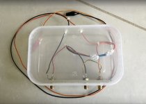
I made up a quick impedance rig as per the REW manual (using and old Indian takeaway box just to add a bit of spice !) and it seems to work fine. I connected it through my Beringer UMC202HD (Headphone port, line out was too noisy) and REW did the rest. I check with a 1% 6.8Ohm resistor as a load (sense is a 1% 2W 100ohms resistor).

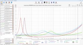
Here are the measurements of the three drivers I am using. All three drivers (SB WO24P-4, Model EM1308 and Morel ET448) were initially measured in place with the box screwed close (it a sealed box design around 40L), I then also measured the woofer with the back left off but with the stuffing still in place.
Here's the results, I have added the published data for reference which seems to be slightly higher in all cases -

Looks OK I think, the in-box sealed measurement is the one that I will use in the crossover modelling, only minor issue is a slight wrinkle at 70hz otherwise it is pretty smooth. Should I be worried about that 70hz wrinkle ?
I will do the whole measurements again to be sure they are correct over the weekend with a fresh calibration but the system works. I may event try to get TS parameters but don't need then now so not a priority. I may also remove the stuffing and test with an empty box to see if I get closer to the published curve but again not a priority.
I made up a quick impedance rig as per the REW manual (using and old Indian takeaway box just to add a bit of spice !) and it seems to work fine. I connected it through my Beringer UMC202HD (Headphone port, line out was too noisy) and REW did the rest. I check with a 1% 6.8Ohm resistor as a load (sense is a 1% 2W 100ohms resistor).

Here are the measurements of the three drivers I am using. All three drivers (SB WO24P-4, Model EM1308 and Morel ET448) were initially measured in place with the box screwed close (it a sealed box design around 40L), I then also measured the woofer with the back left off but with the stuffing still in place.
Here's the results, I have added the published data for reference which seems to be slightly higher in all cases -

Looks OK I think, the in-box sealed measurement is the one that I will use in the crossover modelling, only minor issue is a slight wrinkle at 70hz otherwise it is pretty smooth. Should I be worried about that 70hz wrinkle ?
I will do the whole measurements again to be sure they are correct over the weekend with a fresh calibration but the system works. I may event try to get TS parameters but don't need then now so not a priority. I may also remove the stuffing and test with an empty box to see if I get closer to the published curve but again not a priority.
Nice work. Imho, impedance measurements are highly underrated as diagnostic tools as well.
Considering how important impedance is to the success of diy audio, maybe this site should sell a basic jig. A headphone/mic plug, a tiny resistor, and a bit of wire could be made super cheap, even in a kit style with instructions. I made my own with scraps and a 100ohm for maybe 2 dollars. Even at $10 it would be worth it over the dats if all you wanted was impedance.
Probably applicable… i made it for Fuzzmeasure, but basically the same as i used when manually measuring T/S


I noiw use Smith+Larson Woofer Tester 2 (unfortunately NLA, the best affordable tester IMO) which came with a little current amp… the jog mkakes the voltage ampin the computer act like a current amp.
dave
I noiw use Smith+Larson Woofer Tester 2 (unfortunately NLA, the best affordable tester IMO) which came with a little current amp… the jog mkakes the voltage ampin the computer act like a current amp.
dave
@planet10 looks good, also looks like the same circuit as the one I used except the calibration resistor is just connected instead of the driver. In REW you calibrate open circuit, closed circuit and then with the resistor. I used a 6.8ohm 1% 2w speaker for calibration check and it seemed to calculate correctly. The REW manual suggests using a 100ohm load for headphone output but 1k ohm for line out but suggests line out has more noise and is less accurate.
https://www.roomeqwizard.com/help/help_en-GB/html/impedancemeasurement.html
- Home
- Loudspeakers
- Multi-Way
- Impedance Measurement