I like restoring turntables, I find it a bit meditative compared to my daily grind. I like building new plinths and such but always make sure I can restore it back to its original build. Making a new plinth is easy for some players like my Thorens TD-150, just a simple wooden box (ash in this case).

Others has proven more challenging like my Technics SL-23.

My latest object is a Thorens TD-115 MkII. I bought it fairly cheap at an online auction and it looked quite alright when I picked it up. The previous owner talked a bit about having problems to get it running at 45 rpm but i didn't pay too much attention. I bought it to have something to work on but it would turn out to be much worse than I initially anticipated but more about that later. I was not planning on making a new plinth for this turntable. The original plinth in a quite complex thing in plastics with a very special dust-cover design. I just wanted to restore it but why the TD-115 MkII? Well it is quite interesting functionality-wise and got some great highlights technology-wise.

You either love or hate the original design. I like the sliding buttons like the ones on the TD-125 but I don't like the overall plastic feel. I like support for 78 rpm, the suspension and the option of fully manual or semi automatic operation (with a friction free velocity sensing electronic shut-off, stopping the motor and raising the tonearm). I like the motor, the speed control electronics with load correction, fairly low wow/flutter and rumble figures.
But my turntable, after closer inspection, turned out to be in quite sad condition. One of the holding tabs on the dust-cover was nicked and several plastic pieces on the raising mechanism was broke. Something was seriously wrong with the electronics and the platter bearing was probably shot. One of the buttons on the control panel was bust because someone probably tried to clean it with acetone (what looks like brushed aluminum is just paint).
But the tone arm seemed OK and all the electromechanical parts under the control-panel seemed complete and functional so I started to play with the idea of reusing as much of the original parts as possible and make a new plinth and dust-cover. I was not too worried about the plinth but I wanted to keep the dust-cover design (being able to put the turntable up against a wall) and that was quite a challenge. It took me quite some time to come up with a plan of attack and I would take it step by step...
This thread is me documenting this build in case anyone want to try something similar. A word of warning, don't even try if you value your time more than tinkering in the shop. I really enjoy this kind of work but this build took me close to six month to complete (approximately around 100 hours of work).
Others has proven more challenging like my Technics SL-23.
My latest object is a Thorens TD-115 MkII. I bought it fairly cheap at an online auction and it looked quite alright when I picked it up. The previous owner talked a bit about having problems to get it running at 45 rpm but i didn't pay too much attention. I bought it to have something to work on but it would turn out to be much worse than I initially anticipated but more about that later. I was not planning on making a new plinth for this turntable. The original plinth in a quite complex thing in plastics with a very special dust-cover design. I just wanted to restore it but why the TD-115 MkII? Well it is quite interesting functionality-wise and got some great highlights technology-wise.
You either love or hate the original design. I like the sliding buttons like the ones on the TD-125 but I don't like the overall plastic feel. I like support for 78 rpm, the suspension and the option of fully manual or semi automatic operation (with a friction free velocity sensing electronic shut-off, stopping the motor and raising the tonearm). I like the motor, the speed control electronics with load correction, fairly low wow/flutter and rumble figures.
But my turntable, after closer inspection, turned out to be in quite sad condition. One of the holding tabs on the dust-cover was nicked and several plastic pieces on the raising mechanism was broke. Something was seriously wrong with the electronics and the platter bearing was probably shot. One of the buttons on the control panel was bust because someone probably tried to clean it with acetone (what looks like brushed aluminum is just paint).
But the tone arm seemed OK and all the electromechanical parts under the control-panel seemed complete and functional so I started to play with the idea of reusing as much of the original parts as possible and make a new plinth and dust-cover. I was not too worried about the plinth but I wanted to keep the dust-cover design (being able to put the turntable up against a wall) and that was quite a challenge. It took me quite some time to come up with a plan of attack and I would take it step by step...
This thread is me documenting this build in case anyone want to try something similar. A word of warning, don't even try if you value your time more than tinkering in the shop. I really enjoy this kind of work but this build took me close to six month to complete (approximately around 100 hours of work).
Last edited:

My first question was selection of wood for the plinth? I had a slipmat in cork that I never managed to match color-wise against any of my other turntables. So I took the opportunity to color match it against some European oak. Next up was a bottom of black MDF but the suspension is fitted in elongated holes in the stock plinth and I had to emulate it somehow. I would also prefer something better to screw into than MDF. The solution was to sandwich the MDF bottom with a thin layer of plywood (I would have preferred beech plywood but my suppler cant get it from Russia due to the war with Ukraine so it had to be pine plywood instead).


I tried to emulate the look of Thorens wooden plinths (TD-125 & TD-126) and used my CNC for some detail work for cutouts and what will be the dust-cover mechanism.

Next up was designing some 3D printed parts, mounts for power supply, motor, electronics, connectors etc. And a first try-fit...


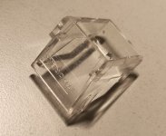
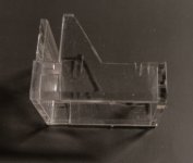
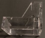
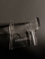
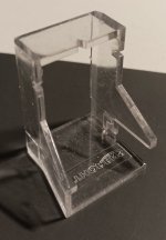
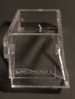
So far so good, next up was fixtures for the dust-cover including the original springs and adjustment screws. I decided to make it out of black acrylics machined with my CNC.


I hope it is fairly obvious how this is supposed to work, it will be complemented with additional 3D-printed parts...

I tried to emulate the look of Thorens wooden plinths (TD-125 & TD-126) and used my CNC for some detail work for cutouts and what will be the dust-cover mechanism.
Next up was designing some 3D printed parts, mounts for power supply, motor, electronics, connectors etc. And a first try-fit...
So far so good, next up was fixtures for the dust-cover including the original springs and adjustment screws. I decided to make it out of black acrylics machined with my CNC.
I hope it is fairly obvious how this is supposed to work, it will be complemented with additional 3D-printed parts...
Next up was actually the electromechanical parts under the control panel but lets start with the electronics. The controller board had a green jumper wire soldered to it and one 4.7V zener diode was replaced with a 5.3V (and some other fairly poor work with replacing electrolytes).

The only copy I could find of the service manual was in German, this is my quick translation of some relevant text and the schematics (with the green jumper wire penciled in):

THORENS SERVICE Service manual TD 115 MK II Record player
ELECTRONICS
9. Circuit description
a) Power supply
The power supply supplies three direct voltages:
approx. +18V
+9.3V +/-5%
+4.7V +/-5%
b) Speed selection electronics
The +4.7V supply forms the reference voltage source for determining the speed. The exact speeds are adjusted using the controllers R238 (33 1/3 rpm), R240 (45 rpm), R242 (78 rpm), whereby the controller R1 should be in the middle position. The voltage taken from the base resistor R223 of the drive motor is used for slip compensation via the amplifier Z 202-3. The controlled variable is added to the reference voltage via R231 and D208. The motor runs as much faster as the belt slip as the load increases.
c) Drive electronics
The tacho signal from the tacho generator G of the drive motor M reaches the inputs of the limiter amplifier Z201-1, which converts the sinusoidal signal into a square wave signal. The monostable flip-flop Z201-2 is controlled via a differentiating element C203 and R206, the output pulses (1) of which are short compared to the period of the tacho signal. The differentiating element C206-R211 and T202 convert this signal into switching pulses (4) which briefly switch the field effect transistor T203 once per tacho period. Z201-4 generates a sawtooth voltage (3) during each tacho period, the amplitude of which is a measure of the speed. The sawtooth generator is reset by a pulse (2) from the monostable flip-flop Z201-3. For reasons of controller stability, a resistor R216 must be connected in parallel to C208.
Shortly before the end of the tachometer period, the instantaneous amplitude of the sawtooth voltage is passed on to C209 by briefly switching through T203 (sample hold circuit). This ensures that the actual value is measured and saved once per tachometer period. If the tachometer period changes due to speed deviations, the voltage value passed on to C209 changes in the same way and the motor is adjusted by the voltage change. D201a ensures that C209 is charged immediately when starting up. The amplifier Z202-1 with T204, which controls the DC motor M, becomes a PI controller through the negative feedback network C210 and R221. The reference voltage applied to connection 2 of Z202-1 determines the speed. The RC element C211—R222 provides interference suppression for the motor. For reasons of temperature stability, R214, R223, R235 and R236 must be metal film resistors.
d) End switch-off
In the playback area of the record, the optical path between the light-emitting diode D302 and the photodiode D301 is interrupted by a shutter. The light barrier only becomes active near the end grooves. By designing the shutter accordingly, a slanted window has been created, through which the sound head travels about 30 mm. The direct current coming from the photodiode D301, which slowly changes according to the groove pitch of the record, is fed to Z202-4. As long as the field effect transistor T206 has not yet switched, Z202-4 acts as a voltage follower. Once per revolution of the turntable, the clock control [A] briefly switches the field effect transistor T206 to conduction and thus the base point of the capacitor C217 to 0-volt potential. The capacitor, which was still charged to the potential of the input voltage present during the previous switching process, now receives the input level difference as a charge. This charging pulse from C217 is amplified via the negative input of Z202-4. The ratio of the resistors R250/R249 determines the amplification. A positive pulse is received at the output of Z202-4 once per revolution, the magnitude of which is proportional to the groove pitch. In the end grooves with a level difference of up to 10 times greater than the sensor, the output pulse of Z202-4 reaches such a magnitude that the threshold of the following Zener diode D209 is exceeded and the threshold circuit T207-T208 is switched, which holds itself. 11 T209 controls the holding magnet and T210 stops the motor by raising the reference voltage for Z202-1. When the tone arm is raised, contact S1 switches the capacitor C217 to 0 potential and the limit switch is no longer active. The device only switches off if the tone arm moves very violently, as the circuit with Z202-4 then acts as a differentiator. If the tonearm is swung from the record against the support in the lowered position, the light barrier window is also released and the device switches off.
When switching on, the threshold switch is set by a charge surge of the capacitor C221 via D210 so that the device does not start.
When switching off, the capacitor C221 immediately discharges via the diode D210a so that the device can be switched on again more quickly without starting.
e) Clock control for limit switch
For one turn of the disc (33 rpm) the tachometer receives 810 mono-flop pulses from the output of Z201-2. These pulses are processed by the counter Z203.
At exactly 800 pulses the outputs 5, 8 and 9 have H states, which are linked via the diode AND gate D213, D214 and D215, where a pulse appears once per revolution. The reset pulse for the counter is via an RS-flip-flop, which is formed from two NOR-gates of the IC Z204 and is controlled by the diode gate and the clock pulse. The FET switch T206 is operated via a second RS-flip-flop of the Z204, which is controlled by the reset pulse and the counter output 5.
10. Adjustment
The exact speed is adjusted using a strobe disk, which can be ordered as an accessory from THORENS. The controller R1 remains in the middle position. First adjust the speed to 33 1/3 rpm with R238, then 45 rpm with R240 and 78 rpm with R242. The adjustment sequence must be strictly adhered to.
With the aperture open (tone arm in the rest or locked position), a voltage of 1.8 volts is set at measuring point using the controller R246. If the tone arm is in the playback area of the record, the shutter is closed and the voltage at measuring point is about 0.48V. If the limit switch is set at the wrong point on the record, the tone arm is locked using the gauge on the back cover so that the needle tip is 48 mm from the center of the turntable. The angled window of the shutter (7 883 008) is now adjusted in the light barrier so that the voltage at measuring point has dropped by just 0.1V to 1.7V.
To make a long story short, the reference voltage 4.7V seems quite crucial, right? It was not 4.7V, closer to 4.3V on my board. Bypassing R237 and swapping D206 to a 5.3V zener IS NOT THE CORRECT WAY TO GET THE REFERENCE VOLTAGE UP TO 4.7V (especially if such a hack only works for 33.3 rpm)! You might question the whole construction using an op-amp to generate the reference voltage and the multitude of flip-flops and other analog logic's to get it to work but I found it quite charming. I restored all components back to their original values, payed a little extra for an axial capacitor, replaced ICs with IC-sockets and plugged in new military grade ICs in the sockets and everything worked just as it should. It was then easy to calibrate all speeds (33.3, 45 & 78 rpm) and auto shut-off according to specification. My oscilloscope was quite helpful but it should have been enough with a multi-meter and some common sense...
The only copy I could find of the service manual was in German, this is my quick translation of some relevant text and the schematics (with the green jumper wire penciled in):
THORENS SERVICE Service manual TD 115 MK II Record player
ELECTRONICS
9. Circuit description
a) Power supply
The power supply supplies three direct voltages:
approx. +18V
+9.3V +/-5%
+4.7V +/-5%
b) Speed selection electronics
The +4.7V supply forms the reference voltage source for determining the speed. The exact speeds are adjusted using the controllers R238 (33 1/3 rpm), R240 (45 rpm), R242 (78 rpm), whereby the controller R1 should be in the middle position. The voltage taken from the base resistor R223 of the drive motor is used for slip compensation via the amplifier Z 202-3. The controlled variable is added to the reference voltage via R231 and D208. The motor runs as much faster as the belt slip as the load increases.
c) Drive electronics
The tacho signal from the tacho generator G of the drive motor M reaches the inputs of the limiter amplifier Z201-1, which converts the sinusoidal signal into a square wave signal. The monostable flip-flop Z201-2 is controlled via a differentiating element C203 and R206, the output pulses (1) of which are short compared to the period of the tacho signal. The differentiating element C206-R211 and T202 convert this signal into switching pulses (4) which briefly switch the field effect transistor T203 once per tacho period. Z201-4 generates a sawtooth voltage (3) during each tacho period, the amplitude of which is a measure of the speed. The sawtooth generator is reset by a pulse (2) from the monostable flip-flop Z201-3. For reasons of controller stability, a resistor R216 must be connected in parallel to C208.
Shortly before the end of the tachometer period, the instantaneous amplitude of the sawtooth voltage is passed on to C209 by briefly switching through T203 (sample hold circuit). This ensures that the actual value is measured and saved once per tachometer period. If the tachometer period changes due to speed deviations, the voltage value passed on to C209 changes in the same way and the motor is adjusted by the voltage change. D201a ensures that C209 is charged immediately when starting up. The amplifier Z202-1 with T204, which controls the DC motor M, becomes a PI controller through the negative feedback network C210 and R221. The reference voltage applied to connection 2 of Z202-1 determines the speed. The RC element C211—R222 provides interference suppression for the motor. For reasons of temperature stability, R214, R223, R235 and R236 must be metal film resistors.
d) End switch-off
In the playback area of the record, the optical path between the light-emitting diode D302 and the photodiode D301 is interrupted by a shutter. The light barrier only becomes active near the end grooves. By designing the shutter accordingly, a slanted window has been created, through which the sound head travels about 30 mm. The direct current coming from the photodiode D301, which slowly changes according to the groove pitch of the record, is fed to Z202-4. As long as the field effect transistor T206 has not yet switched, Z202-4 acts as a voltage follower. Once per revolution of the turntable, the clock control [A] briefly switches the field effect transistor T206 to conduction and thus the base point of the capacitor C217 to 0-volt potential. The capacitor, which was still charged to the potential of the input voltage present during the previous switching process, now receives the input level difference as a charge. This charging pulse from C217 is amplified via the negative input of Z202-4. The ratio of the resistors R250/R249 determines the amplification. A positive pulse is received at the output of Z202-4 once per revolution, the magnitude of which is proportional to the groove pitch. In the end grooves with a level difference of up to 10 times greater than the sensor, the output pulse of Z202-4 reaches such a magnitude that the threshold of the following Zener diode D209 is exceeded and the threshold circuit T207-T208 is switched, which holds itself. 11 T209 controls the holding magnet and T210 stops the motor by raising the reference voltage for Z202-1. When the tone arm is raised, contact S1 switches the capacitor C217 to 0 potential and the limit switch is no longer active. The device only switches off if the tone arm moves very violently, as the circuit with Z202-4 then acts as a differentiator. If the tonearm is swung from the record against the support in the lowered position, the light barrier window is also released and the device switches off.
When switching on, the threshold switch is set by a charge surge of the capacitor C221 via D210 so that the device does not start.
When switching off, the capacitor C221 immediately discharges via the diode D210a so that the device can be switched on again more quickly without starting.
e) Clock control for limit switch
For one turn of the disc (33 rpm) the tachometer receives 810 mono-flop pulses from the output of Z201-2. These pulses are processed by the counter Z203.
At exactly 800 pulses the outputs 5, 8 and 9 have H states, which are linked via the diode AND gate D213, D214 and D215, where a pulse appears once per revolution. The reset pulse for the counter is via an RS-flip-flop, which is formed from two NOR-gates of the IC Z204 and is controlled by the diode gate and the clock pulse. The FET switch T206 is operated via a second RS-flip-flop of the Z204, which is controlled by the reset pulse and the counter output 5.
10. Adjustment
The exact speed is adjusted using a strobe disk, which can be ordered as an accessory from THORENS. The controller R1 remains in the middle position. First adjust the speed to 33 1/3 rpm with R238, then 45 rpm with R240 and 78 rpm with R242. The adjustment sequence must be strictly adhered to.
With the aperture open (tone arm in the rest or locked position), a voltage of 1.8 volts is set at measuring point using the controller R246. If the tone arm is in the playback area of the record, the shutter is closed and the voltage at measuring point is about 0.48V. If the limit switch is set at the wrong point on the record, the tone arm is locked using the gauge on the back cover so that the needle tip is 48 mm from the center of the turntable. The angled window of the shutter (7 883 008) is now adjusted in the light barrier so that the voltage at measuring point has dropped by just 0.1V to 1.7V.
To make a long story short, the reference voltage 4.7V seems quite crucial, right? It was not 4.7V, closer to 4.3V on my board. Bypassing R237 and swapping D206 to a 5.3V zener IS NOT THE CORRECT WAY TO GET THE REFERENCE VOLTAGE UP TO 4.7V (especially if such a hack only works for 33.3 rpm)! You might question the whole construction using an op-amp to generate the reference voltage and the multitude of flip-flops and other analog logic's to get it to work but I found it quite charming. I restored all components back to their original values, payed a little extra for an axial capacitor, replaced ICs with IC-sockets and plugged in new military grade ICs in the sockets and everything worked just as it should. It was then easy to calibrate all speeds (33.3, 45 & 78 rpm) and auto shut-off according to specification. My oscilloscope was quite helpful but it should have been enough with a multi-meter and some common sense...
Next up some additional 3D-printed parts to host all the electromechanical parts under the control panel. I had to print these parts a couple of times to get it right, I used a caliper to transfer the original measures and then used CAD to make models fitting inside my wooden plinth. It might sound quite easy and straight forward but it takes time and patience to get it right.


I continued with black acrylics in the back but used acrylic mirrors for the control panel and buttons. The panels are mounted with 28 micro magnets, easy to place and easy to remove. I carved the labels from behind and filled with acrylic paint. The acrylic button overlays was then mounted with double sided tape (no original parts was hurt during this build). Panels and button overlays was machined with my CNC.


That was the easy part, next up is the dust-cover. This is what the mounts look like finished, including adjustment screws in the rear bottom of the plinth. And the rear connectors and power socket.


I continued with black acrylics in the back but used acrylic mirrors for the control panel and buttons. The panels are mounted with 28 micro magnets, easy to place and easy to remove. I carved the labels from behind and filled with acrylic paint. The acrylic button overlays was then mounted with double sided tape (no original parts was hurt during this build). Panels and button overlays was machined with my CNC.
That was the easy part, next up is the dust-cover. This is what the mounts look like finished, including adjustment screws in the rear bottom of the plinth. And the rear connectors and power socket.
Last edited:
The dust-cover was quite tricky to fabricate. I used acrylic panels and glued them with Acrifix 192 (and routed the edges on a router board finishing witch a polishing wheel). It was the first time I used the product and the result was OK but not perfect. I have plans for another dust-cover with a different design but I save that for the winter. 🙂
I also polished the platter and replaced the platter bearing. It was only spinning for 30 sec when I bought it and the bearing turned out to be totally shot. Polishing did help (got it up to 2.5 min) but the axis was pitted and it sometimes made some noise so I replaced it. The platter now spins for 3 min and 29 sec. I am pretty happy with the result, especially that I managed to get the dust-cover working (it is even detachable just like the original) and that it is clear instead of smoked.


This was a fun project but much more work than I anticipated. Still a lot of work to be done like new dust-cover and selection of high compliant stylus with matching cartridge. But first some relaxation with some jazz...
I also polished the platter and replaced the platter bearing. It was only spinning for 30 sec when I bought it and the bearing turned out to be totally shot. Polishing did help (got it up to 2.5 min) but the axis was pitted and it sometimes made some noise so I replaced it. The platter now spins for 3 min and 29 sec. I am pretty happy with the result, especially that I managed to get the dust-cover working (it is even detachable just like the original) and that it is clear instead of smoked.
This was a fun project but much more work than I anticipated. Still a lot of work to be done like new dust-cover and selection of high compliant stylus with matching cartridge. But first some relaxation with some jazz...
Last edited:
Ps. Speed control is now fairly accurate and wow according to spec (and even better on 45 and 78 rpm).

I can't say I find the 115 attractive, but you've certainly made a nice job of making it look its best and fixing problems added by bodgers. Well done.
Thanks for your kind words, EC8010. I totally get why the TD-115 get so little love, but it is growing on me. The way it operates (especially in semi-automatic mode) is a bit quirky but make sense. And who doesn't want friction free auto-stop?
It is built much like a mechanical toy, with the ratcheting mechanism for the lift and power button linkage, but it is functional and serviceable. Some parts are quite fragile and made of plastic, but it is not too hard to replace them with parts you can make yourself (you can even take the opportunity to improve the design). Motor and control circuits are rock solid and easy to replace if needed (PCB only contain four IC and all are ready available). The platter bearing is a bit dinky, but easy and cheap to replace if needed.
My major concern is the tonearm. The ISOTRACK (TP30 with end tube TP70) is probably a fine tonearm, but I would have preferred a tonearm without a rare to come by "wand" and with a "standard" H-4 bayonet mount instead. The effective mass of the TP30 + TP70 is only 7.5g and the way cartridges mount to the TP70 limits the selection of suitable cartridges even further.
So I will take the opportunity to ask for help or guidance when it comes to selection of cartridge and stylus. I got a limited selection of high compliance combos, and none mount on the TP70. I got a Shure M75-6S (type 1, "clip mount") cartridge without stylus in good condition. Furthermore, I am tempted to buy an aftermarket N91ED stylus and pair it with the M75-6S. I think it would be a solid combo, just not very high compliant. Another more compliant combo would be to pair it with an N95HE styli, but I am not sure if it will fit the M75-6S? Some say it does, but I have no solid proof. Does anyone know if it will fit or not (M75-6S + N95HE)?
And one more thing, does anyone have the mounting gauge for the TP30 + TP70 combo? If I could find the measurements, I could make a 3D-printable model of this hard to come by item. 🙂
Last edited:
Many years ago, I had an M95ED; a very compliant cartridge that needed a low mass, low friction arm such as the SME3009/S2. I used it in a unipivot. In all your work, did you strip the arm down? I ask because I acquired the arm from a Thorens TD166 and its horizontal bearing was simply a bicycle wheel cup and cone arrangement. I discovered this when an Ortofon FF15E decided one day it couldn't drag said arm across record. When I opened the bearings up the surfaces were more badly worn and pitted than any bicycle bearings I had ever seen; I suspect they weren't hardened. The point I'm leading up to is that I doubt that the arm is good enough for an N95HE stylus. I could be wrong, but I suggest you have a look at the bearings. Be warned that disturbing arm wiring is fraught with trouble - it's ever such fine stuff. From memory, the M95 body (not the plastic bits, but the metal department) was much more rounded than the rectangular box of the M75. I doubt that an M95 stylus would fit.
Thanks for your reply, EC8010. Interesting information about the tonearm bearings of the TD-166, but the TD-166 is equipped with the TP-11 + TP-21 combo. It looks a bit similar to the TP-30 + TP-70 combo on the TD-115 (they both got "wands"), but they are different animals.
TP-11 (left) vs. TP-30 (right):

.JPG")
There are not much information about the TP30 tonearm on the Internet (surprisingly) but the user's manual states "... the improved Isotrack tonearm with fully shock-protected jewel bearings. The spring suspended bearings flex in all directions and so prevent any possible damage to the arm from external forces." is also state "Do not attempt to tighten the tonearm bearing screws."
I agree that fitting a N95 stylus to a M75 cartridge seems farfetched, but the M75 Type 1 (snap in) is supposed to accept a whole slew of different styli, including N95 and N97 (even V15 III)! At least according to Paladin & Co. in this thread over at VinylEngine. I don't know if that is true or not, but it would be quite cool if it was. That's why I was contemplating buying a cheap aftermarket stylus just to verify if it works or not? But even better if someone here at DIYAudio already know and wants to share their experience. 😉
TP-11 (left) vs. TP-30 (right):
There are not much information about the TP30 tonearm on the Internet (surprisingly) but the user's manual states "... the improved Isotrack tonearm with fully shock-protected jewel bearings. The spring suspended bearings flex in all directions and so prevent any possible damage to the arm from external forces." is also state "Do not attempt to tighten the tonearm bearing screws."
I agree that fitting a N95 stylus to a M75 cartridge seems farfetched, but the M75 Type 1 (snap in) is supposed to accept a whole slew of different styli, including N95 and N97 (even V15 III)! At least according to Paladin & Co. in this thread over at VinylEngine. I don't know if that is true or not, but it would be quite cool if it was. That's why I was contemplating buying a cheap aftermarket stylus just to verify if it works or not? But even better if someone here at DIYAudio already know and wants to share their experience. 😉
Last edited:
Do you mean this one? If you still need it I can make a drawing with all the dimensions in the next days.And one more thing, does anyone have the mounting gauge for the TP30 + TP70 combo?
Nice job, your TTs look wonderful.
I tried my best... and I hope that I have not made a lot of mistakes.
All the dimensions in mm.
In case that something it's not clear, just ask.

All the dimensions in mm.
In case that something it's not clear, just ask.
Attachments
-
 IMG_20250227_005542_cr.jpg287.5 KB · Views: 28
 -
 IMG_20250227_183143_cr.jpg417.1 KB · Views: 24
 -
 IMG_20250227_183202_cr.jpg378.8 KB · Views: 25
 -
 IMG_20250227_183327_cr.jpg185 KB · Views: 23
 -
 IMG_20250227_183318_cr.jpg186.4 KB · Views: 27
 -
 IMG_20250227_183308_cr.jpg281.6 KB · Views: 21
 -
 IMG_20250227_183341_cr.jpg159.4 KB · Views: 27
Last edited:
Amazing shadowplay62! Thank you so much. I will share the 3D model so you can compare it with the original 🙂
I kind of forgot this thread until I now made some updates to this build. Excuse me shadowplay62, I will get going on the CAD model...😳
I still love this TT and it has become my daily driver. There are a couple of details I wanted to continue work on and I have just finished the first two... First up was the stroboscope. The way it woks is shining through slots in the platter. The upper slots are for 50 Hz and the lower ones for 60 Hz. Whats been a bit frustrating is that the upper slots work great with the stock slipmat but not so much with my aftermarket one in cork (it covers the slots from above). It is also a bit frustrating that my mains frequency fluctuate a bit. So what I wanted was a stable stroboscope that would work with the lower 60 Hz slots. Searching the net led me to Vinyengines DIY Strobe, a nice circuit but I wanted something I could switch between 50 and 60 Hz. I finally found Retronics DIY: Mini turntable strobe and it was exactly what I was looking for!
My first idea was to daisy-chain two of those and make a new stroboscope with LEDs for both the upper and lower slots. It got a bit complicated so a limited my first implementation to the lower slots (with room for future improvements). I designed a through-hole board with a separate AC and DC section (only one board need the AC components if daisy-chaining more than one board). I de-soldered the stock stroboscope from the mains pins and added extra leads from the transformers secondary side.


Next up was designing a new housing for the LEDs and fitting the stock mount points. Orange LEDs looked exactly as stock so I went with something different just to make it obvious that is has been customized.😎


The black top and bottom is to prevent light through the upper 50 Hz slots and reflections from under the platter into my custom mirror like control panel. I am very pleased with the end result. The stroboscope is rock solid and does not drift with the mains frequency. Next upgrade might be LED lights all around the platter.🤣

Ps. The TT is currently rocking a M75 Type 1 with a Analogis Black Diamond stylus, nude elliptical 1.0g - 1.5g - low tracker. It tracks well even as low as 0.75g but I am running it @ 1.0g.
I still love this TT and it has become my daily driver. There are a couple of details I wanted to continue work on and I have just finished the first two... First up was the stroboscope. The way it woks is shining through slots in the platter. The upper slots are for 50 Hz and the lower ones for 60 Hz. Whats been a bit frustrating is that the upper slots work great with the stock slipmat but not so much with my aftermarket one in cork (it covers the slots from above). It is also a bit frustrating that my mains frequency fluctuate a bit. So what I wanted was a stable stroboscope that would work with the lower 60 Hz slots. Searching the net led me to Vinyengines DIY Strobe, a nice circuit but I wanted something I could switch between 50 and 60 Hz. I finally found Retronics DIY: Mini turntable strobe and it was exactly what I was looking for!
My first idea was to daisy-chain two of those and make a new stroboscope with LEDs for both the upper and lower slots. It got a bit complicated so a limited my first implementation to the lower slots (with room for future improvements). I designed a through-hole board with a separate AC and DC section (only one board need the AC components if daisy-chaining more than one board). I de-soldered the stock stroboscope from the mains pins and added extra leads from the transformers secondary side.
Next up was designing a new housing for the LEDs and fitting the stock mount points. Orange LEDs looked exactly as stock so I went with something different just to make it obvious that is has been customized.😎
The black top and bottom is to prevent light through the upper 50 Hz slots and reflections from under the platter into my custom mirror like control panel. I am very pleased with the end result. The stroboscope is rock solid and does not drift with the mains frequency. Next upgrade might be LED lights all around the platter.🤣
Ps. The TT is currently rocking a M75 Type 1 with a Analogis Black Diamond stylus, nude elliptical 1.0g - 1.5g - low tracker. It tracks well even as low as 0.75g but I am running it @ 1.0g.
The other update was a new dust-cover I have been contemplating for a while. I envisioned it as the "levitating dust-cover", one piece bent and hinged on a piece of stainless steel without any sides (my dust-covers are more about tonearm protection than dust protection).😆
This is the end result, it is still detachable and I had to switch color of the LEDs in my amp to match the new stroboscope.🤣


This is the end result, it is still detachable and I had to switch color of the LEDs in my amp to match the new stroboscope.🤣
- Home
- Source & Line
- Analogue Source
- My custom built Thorens TD-115 MkII