Dear All
I am new for DIY the tube amp.
Now I've already finished the PCB with the circuit as in the attached file.
After I try supply the AC power 220V to it, the problem happen when I adjust the volume of input signal from 0 to max.
There is noise during the volume is middle position ( between 0 - max position of POT ) and I measured grid bias of EL84 it drop below -12V ( -16 ~ -23V) which is happen when middle position of POT. The bias is fixed when I adjust the volume POT it will be changed ?
Could you let me know what is cause of this problem ?
Thank you
Attachments
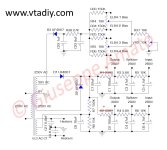
Why such a giant 47k value for a gridstopper? A mistake?
Unrelated to the issue but there should be a fixed value resistor in parallel to the pot.
Unrelated to the issue but there should be a fixed value resistor in parallel to the pot.
Last edited:

I'm not so sure that is unrelated. One possible cause of the issue would be a rotten potmeter, a 1 Mohm resistor from the wiper to the ground would then ensure that at least the biasing stays more or less normal when the wiper loses contact.
Why have you changed R1 & R2 to 1k? Have you measured anode voltages when volume pot is in middle position?Now I've already finished the PCB with the circuit as in the attached file.
I change because if I used 330 the voltage more than 300 V (up to 320V ) I think it more than bias point I set then I try to use 1K it can be 300 V as I needWhy have you changed R1 & R2 to 1k? Have you measured anode voltages when volume pot is in middle position?
The issue relate to this resistor ?
Check that B+ voltages (300V, 290V, 280V) do not sag too much when you change the volume.
I try to change the grid stopper and check B+ it not sag too much.
I suppose the problem may from parasitic.
If the PCB have 2 layer it cause the parasitic?
I suppose the problem may from parasitic.
If the PCB have 2 layer it cause the parasitic?
The grid stopper in this case acts as low pass filter using Miller effect so do not lower it too much. High grid stopper resistance adds noise but it should not have any impact on your issue.
OK I already fix this issue.
It cause from input copper track to input stage.
It may too long before input stage.
Thank you for any advice.
Best Regard
It cause from input copper track to input stage.
It may too long before input stage.
Thank you for any advice.
Best Regard
I think it could be the NFB oscillation in the 50-150KHz region. With the volume pot in the middle the miller cap of the 12ax7 may stop the oscillation,
Do you have a scope? If so you will be able to see it on the speaker output if that's the issue. If you don't disconnect the feedback from the 8R tap. The gain will increase a lot, but then is the bias stable.
Last edited:
Without putting the circuit on LT spice with model of OPT I would try 22k+100pF in series placed across R15 the first plate resistor. This forms a dominate pole in the amp. You could also move the FB to the 4R tap but leave the speaker on the 8R. This will reduce the open loop gain.
Hi
Sorry but I don't think open loop will be changed, it is the gain with GFB and the GFB rate
Sorry but I don't think open loop will be changed, it is the gain with GFB and the GFB rate
Sorry sir.
This problem still cannot fix.
Please refer to the VDO below.
What is root cause of this problem ?
This problem still cannot fix.
Please refer to the VDO below.
What is root cause of this problem ?
There are other and better ways of limiting frequency response of first gain stage than putting a 47kohm series resistance on the grid.
small cap between anode and ground would do a better job and possibly remove the need for a 500pF cap in the feedback loop.
What I miss in this schematic is ground connection of COM terminal of the secondary side of the output transformer.
Have you followed the schematic to 100% or did you see the schematic fault and connected COM to signal ground at the low impedance ground point of the electrolytics in the power supply?

A

small cap between anode and ground would do a better job and possibly remove the need for a 500pF cap in the feedback loop.
What I miss in this schematic is ground connection of COM terminal of the secondary side of the output transformer.
Have you followed the schematic to 100% or did you see the schematic fault and connected COM to signal ground at the low impedance ground point of the electrolytics in the power supply?
A
Last edited:

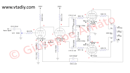
Since you have three gain stages you need to invert phase in the output transformer.
That's not always indicated in a schematic from a producer, but for a DIY it should.
Look at this and think about it, since I suspect you have made some errors in your schemetic.
I doubt that 8 ohm tap shoulf be grounded. 16 ohm tap is more likely to be grounded.
By inverting phase you get this:
COM will be new 16 ohm tap
4 ohm will be new 8 ohm tap
8 ohm will be new 4 ohm tap
16 ohm will be new ground tap

As seen in the schematic the phase are inverted between primary and secondary side.
Have you checked if you connected the right EL84 to the phase indication of the output transformer?
If you mix them you will not get the necessary signal inversion.

That's not always indicated in a schematic from a producer, but for a DIY it should.
Look at this and think about it, since I suspect you have made some errors in your schemetic.
I doubt that 8 ohm tap shoulf be grounded. 16 ohm tap is more likely to be grounded.
By inverting phase you get this:
COM will be new 16 ohm tap
4 ohm will be new 8 ohm tap
8 ohm will be new 4 ohm tap
16 ohm will be new ground tap
As seen in the schematic the phase are inverted between primary and secondary side.
Have you checked if you connected the right EL84 to the phase indication of the output transformer?
If you mix them you will not get the necessary signal inversion.
Last edited:
OK I will try. Then I will inform the result again about the problem.
But I think now my output transformer is inverted between input and output.
But I think now my output transformer is inverted between input and output.
- Home
- Amplifiers
- Tubes / Valves
- Fixed bias has changed after volume position is middle