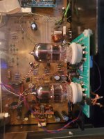
Long ago I have gotten an used Toshiba SC-330 amp.

It has the top cover too but never had the power button, the knobs and the light bulbs for the vumeters.
It played ok for a while then the right channel blew up.
Opening it I found one channel had already the original bjts in the output stage replaced with other types. I replaced them and they blew up again. So I parked the amp and almost forgotten about it.
The last year while I was searching for something else I found my Toshiba.
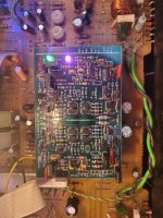
Initial plan was to restore the original circuit but when I seen how the pcb looks I changed my mind.

I started first with putting all the parts apart and cleaning everything and then I opened up the 60vac ct transformer and separated the secondary windings making it a dual 30vac secondary because I wanted to power a ACA amp with each winding.


Then I did some dissipation testing with forced cooling and 60w of heat was manageable.
At this point I decided to draw a new pcb with the ACA on it. And I did.

Then looking closer the ACA wasn’t exactly what I was searching for.
One day Nelson mentioned on the forum that he is planning an F5L so this was the spark to try and use the lateral Alfet mosfets that I got from his giveaway.
Searching a bit I came across the Cubie 3. So this time I drew a main pcb and another pcb for each amp module.
The main pcb includes dc speaker protection, A/B ssr speaker switch which uses the front switch as signal control only, initially it was switching directly the speaker signals.
It includes also vumeter drivers, vumeter backlight adjustment, fan speed control, over temperature control and bias control.


Here is the schematic for the Cubie3 with lateral mosfets, 2 bias settings and standby control in case it overheats because of fan failure. And needs to be turned off.


Appart the Cubie that was oscillating with laterals and needed some extra compensation everything went nice.

The level potentiometers were replaced too with new ones. Now I have to search for some nice knobs.

Each pcb hosts 6 smd leds.

The back panel was cut to make the intake for the fans. The rca and speaker connectors were replaced too. Probably will add a grill because I caught my fingers in the blades a few times when connecting the rca connectors.

At this point I still have a few things to solve.
The fans introduce some noise in the rails so a filter will need to be added in front of them.
Then I can hear some hum in the speakers from a few cm away.
Doing some ffts I seen that I have both 50hz and 100hz components.
At this point I want to search for a toroidal transformer because of the lower radiated electromagnetic field which will help with the 50hz coupling.
There is another reason that I want a toroidal transformer. This trafo has only 100va and with 4ohm loads the rail voltage drops too much.
A 200va toroidal even 300va will fit nicely in the same footprint. Beside this I will get the new transformer with lower voltages which will enable me a higher bias, probably 2x26vac.
Some cap multipliers will be added too.
In this time of the year when you have 40C temps outside a nice ab amp keeps your house cold and pleases you with a very nice sound and a lot of power too if needed.
Never listened to laterals until now and I can say that I didn’t expect them to sound so good.
It has the top cover too but never had the power button, the knobs and the light bulbs for the vumeters.
It played ok for a while then the right channel blew up.
Opening it I found one channel had already the original bjts in the output stage replaced with other types. I replaced them and they blew up again. So I parked the amp and almost forgotten about it.
The last year while I was searching for something else I found my Toshiba.
Initial plan was to restore the original circuit but when I seen how the pcb looks I changed my mind.
I started first with putting all the parts apart and cleaning everything and then I opened up the 60vac ct transformer and separated the secondary windings making it a dual 30vac secondary because I wanted to power a ACA amp with each winding.
Then I did some dissipation testing with forced cooling and 60w of heat was manageable.
At this point I decided to draw a new pcb with the ACA on it. And I did.
Then looking closer the ACA wasn’t exactly what I was searching for.
One day Nelson mentioned on the forum that he is planning an F5L so this was the spark to try and use the lateral Alfet mosfets that I got from his giveaway.
Searching a bit I came across the Cubie 3. So this time I drew a main pcb and another pcb for each amp module.
The main pcb includes dc speaker protection, A/B ssr speaker switch which uses the front switch as signal control only, initially it was switching directly the speaker signals.
It includes also vumeter drivers, vumeter backlight adjustment, fan speed control, over temperature control and bias control.
Here is the schematic for the Cubie3 with lateral mosfets, 2 bias settings and standby control in case it overheats because of fan failure. And needs to be turned off.
Appart the Cubie that was oscillating with laterals and needed some extra compensation everything went nice.
The level potentiometers were replaced too with new ones. Now I have to search for some nice knobs.
Each pcb hosts 6 smd leds.
The back panel was cut to make the intake for the fans. The rca and speaker connectors were replaced too. Probably will add a grill because I caught my fingers in the blades a few times when connecting the rca connectors.
At this point I still have a few things to solve.
The fans introduce some noise in the rails so a filter will need to be added in front of them.
Then I can hear some hum in the speakers from a few cm away.
Doing some ffts I seen that I have both 50hz and 100hz components.
At this point I want to search for a toroidal transformer because of the lower radiated electromagnetic field which will help with the 50hz coupling.
There is another reason that I want a toroidal transformer. This trafo has only 100va and with 4ohm loads the rail voltage drops too much.
A 200va toroidal even 300va will fit nicely in the same footprint. Beside this I will get the new transformer with lower voltages which will enable me a higher bias, probably 2x26vac.
Some cap multipliers will be added too.
In this time of the year when you have 40C temps outside a nice ab amp keeps your house cold and pleases you with a very nice sound and a lot of power too if needed.
Never listened to laterals until now and I can say that I didn’t expect them to sound so good.

Great project. I had one of these also. I gutted it and saved the heat sink and a few other choice parts. I then recycled what was left. Good luck with the build.
It’s a great little chassis. I have a similar SC-335 that I‘ve used for a couple different Class D builds.
Current version is with @abraxalito’s transformer input TDA8932 mono amps.
Fun to build in a vintage chassis. @schultzsch’s Cubie build is next-level awesome, though, with custom fit PCBs and integrated meter control/lighting. Well executed. 😎 I’m certainly a fan of lateral outputs, so even more kudos.
I really liked the front plate since I got it, even if a bit disappointed when it blew up I kept it there and built an AJ to replace it.
Now his time has come again.
When I built this project I had in mind others too.
I won’t share the gerbers online but if someone is interested can send a private message and will get them.
I have a few spare pcbs too but shipping outside Europe gets expensive because of the dimensions.
If you like how the enclosure looks it goes for 100€ or maybe less and you find them in goood shape too.
Take one and build a nice summer amp.
To mention that you will have to do a bit of metal cutting but it’s fun and a Dremel is cheap 🙂
Yours looks nice too. In my amp the pcb wasn’t in a good condition and this was my excuse to try a cfb amp for which I had the parts already.
This is my first cfb and I can say it sounds awesome.
I delayed many times this project in the last year. Now the heat outside pushed me to finish it and I am very glad I did.
This is my first cfb and I can say it sounds awesome.
I delayed many times this project in the last year. Now the heat outside pushed me to finish it and I am very glad I did.
Fantastic project Schultzsch! Love the idea of using the neat looking Toshiba chassis. I purchased an SC-665 with an issue in one channel with the thoughts of gutting it to use for a DIYA project like you did.
Good luck ironing out the small details and enjoy watching the meters dance!

Good luck ironing out the small details and enjoy watching the meters dance!
Nice unit Vunce, I see yours has already a toroidal unit and probably jfets on the input.
First of disassembling it could worth a try increasing a bit the bias and maybe a recap.
Higher bias means forced cooling so you will need to find a place where to attach some fans, maybe on the top cover. You will have to look also for the soa of the output devices at the new bias.
Your heatsink looks like mine and seems to have same fixing holes so probably can be used with my pcbs.
If you can’t move the heatsink towards the front to place the fans on the back like I did, you could keep them on the top cover if they are efficient and use the extra space on the front for some extra filtering.
In your case if you want to use a different placement for the fans first you need to test to see how it works.
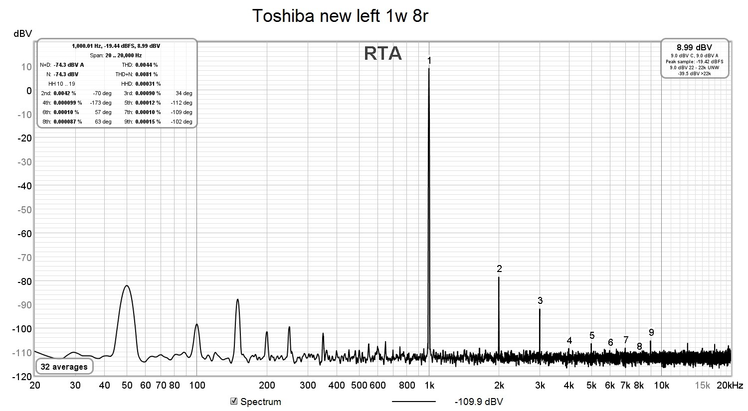
I finally placed all the stuff in the enclosure and took again the measurements.
A lot better. I can say at this point I am happy with the outcome.
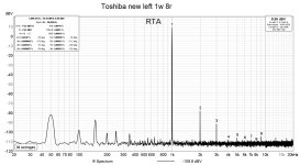
Here is the left channel


And here the right one which has a bit higher noise than the left but it is still very low.

Now with the lower noise floor I can show some nice thd graphs.
The amp was powered with +/-33V and biased at 300ma


A lot better. I can say at this point I am happy with the outcome.
Here is the left channel
And here the right one which has a bit higher noise than the left but it is still very low.
Now with the lower noise floor I can show some nice thd graphs.
The amp was powered with +/-33V and biased at 300ma
Attachments

schultzsch,
Great work! I need to get those boards from you…….
Keep it up and keep us posted.
Cheers,
Greg
Great work! I need to get those boards from you…….
Keep it up and keep us posted.
Cheers,
Greg
- Home
- Amplifiers
- Pass Labs
- New amp, old faceplate