A friend had a Marantz 240 where the speaker protection relay would never engage. Discovered it had some bad transistors on the right channel. Replaced them and the idle output voltage differential went to ~0 Vdc. Relay functions as expected now. Thought I was done.
However, the left channel exhibits clipping at around 4.5 Vdc. None of the transistors seems bad or even particularly weak. There were a few transistors that tested strong and worked after reflowing the solder, and others with no obvious issue.
Someone was in this thing long before me, and there are a few non-standard parts on the relay board.
The signal looks clean until it gets to the point where the signal and feedback mix after the diff amp, and I'm not sure how to suss out what is clipping distortion in the feedback and what is distortion in the desired signal.
Waveforms taken at speaker output across 8 ohm resistive load.
Any ideas?
If you drive amp without a load, what is max output/clipping behavior?
The amp has separate adjustments for both positive and negative output currents--- eg. R541, Q516. Repeat setup as in first first photo and then tweak R541 to see if output improves.
Good luck.
The amp has separate adjustments for both positive and negative output currents--- eg. R541, Q516. Repeat setup as in first first photo and then tweak R541 to see if output improves.
Good luck.
Attachments

I don't have the amp in front of me, but if I run it no-load, no significant current is applied to the resistors on the overcurrent protection transistors, so if I still see clipping, I know the clipping is not coming from the positive side overcurrent detection circuit? But if I don't see clipping, is that a smoking gun for the overcurrent circuit being the problem?
Thanks for the help.
Thanks for the help.
It would certainly be suggestive that current limit is in play. But as the old saw says, nothing certain but death and taxes... 😉
That's for sure.
Finally back in town. Tried the amp with no load on the left channel, and get very similar clipping behavior, except at around +7 V.
The service manual says that improper clipping would be the result of my current peak trim resistors being set improperly (which no-load clipping seems to rule out), or that some transistor Q802-Q805 is open.
If the pre-drivers are able to handle the signal up to ~7 V, and the power transistors are new, strong, and don't appear to be open, I'm guessing something else is open somewhere in the path between the +60 Vdc rail, Q802/Q804 and the output at terminal 19, since the current (I'm guessing) that would be delivered by the power transistors isn't being delivered...
So, Q802/Q804 aren't turnning on or their supply is open.
Thinking out loud here. Will check tomorrow.
Any other thoughts, folks?
I agree with your speculation about possible faults.
I suggest diving both channels simultaneously with the same sine wave signal and using the good channel as reference for expected waveforms when you observe suspicious behavior in the problem channel. No load testing would be easiest, but applying 8 ohm loads might also be revealing.
I suggest diving both channels simultaneously with the same sine wave signal and using the good channel as reference for expected waveforms when you observe suspicious behavior in the problem channel. No load testing would be easiest, but applying 8 ohm loads might also be revealing.
I removed Q516, an MPSA43 NPN. An in-circuit diode test lead me to believe it was ok, and once it was off the board, it appeared to test out reasonably strong.
With a signal applied and Q516 out of the circuit, the premature clipping went away, which was not a surprise. Bingo, right?
However, I then replaced Q516 with an MPSA42 I had lying around (basically an MPSA43 with an extra 100 V of Vce headroom). The clipping came back exactly as before, so apparently Q516 is not the problem (?).
I also removed Q505 from the circuit and applied a signal with Q516 placed. There was no obvious change and the premature clipping was still there.
There does not seem to be any significant drift in any of the neighboring parts, and none the parts in the neighborhood of Q516 or Q505 appear obviously shorted or open, and the traces seem intact.
If something was wrong with my pre-drivers Q507 and Q510 and they weren't passing the signal (shorted or open?) I wouldn't see my waveform at the output.
If Q505 was leaky, it would be pulling up Q507's base and turning off the signal at the first pre-driver stage, or at least doing something that would have gone away (maybe) when Q505 was removed from the circuit.
The power transistors on the + side are new and don't seem to have anything wrong with them...
I am stumped.
I feel like I have all the pieces in front of me, but I can't seem to put the puzzle together.
Rail is sitting at about +58 Vdc, I believe, but I will confirm. The right channel is healthy (rails on right and left channels are supplied from common cans) and the rail voltages look clean.
Since I was able to sidestep the clipping by removing Q516 temporarily, it seems when Q516 is in the circuit, something is causing Q516 to conduct above a certain much-to-low voltage that trimpot R541 does not effect.
Since I was able to sidestep the clipping by removing Q516 temporarily, it seems when Q516 is in the circuit, something is causing Q516 to conduct above a certain much-to-low voltage that trimpot R541 does not effect.
Last edited:
Good sleuthing!
Maybe Q516 has become leaky? Confirm R541 resistance can be adjusted to near 0 Ohm and that then low resistance appears between base, emitter, and R546, etc. I.e. confirm PCB trace integrity.
Also confirm R544 value and trace integrity, eg. 1k resistance between board terminal 18 and collector of Q516.
@BSST I had replaced Q516 with an MPSA43 with no change in circuit operation.
R541 is fully adjustable (though it maxes out at about 2.3 kOhm), as confirmed with a meter in and out of circuit.
The traces look good on on the PCB, and I reflowed the joints in the neighborhood. Nothing really looked like it had gotten hot enough, based on discoloration of nearby board or components, to desolder itself, and the joints I reflowed already looked ok and tested continuous.
I also looked at the pin sockets for the power transistors and cleaned them.
No dice.
I am mystified for the moment. Working my way back through the circuit.
(There were some issues on the Right channel that were solved be reflowing the solder around some of the semiconductors. Perhaps the thing was dropped?)
The saga continues.
Reflowed all the current-leveling/load resistors on the V+ side of the power amp section (R533, R535, R531). No change.
I replaced Q516 (overcurrent detection) with an MPSA42. No change.
I replaced Q505 (predriver overcurrent negative feedback) with an MPSA92. The output looked good for about 10 seconds (???) then went back to the premature clipping. (The old 2N4125 tested ok in my transistor tester, but what's a good way to more thoroughly test a transistor?)
I checked all the load and biasing resistors attached to the V+ side after the differential amplifier and everything checked out with no significant drift.
So maybe the V+ rail snubber caps went leaky and are mis-biasing the predrivers? I replaced C520 (6.8 nF) and C519 (0.1 uF). No change.
Cleaned with steel wool the screws and pins that tie the power transistors to the rest of the circuit. No change.
Swapped the power transistor assembly (V+ side NPNs Q802, Q804, and cross-over compensation circuit transistor Q801) right channel for left channel. No change.
Since we're clipping at a repeatable, constant voltage instead of seeing a problem that scales with applied voltage, the problem must be a semi-conductor issue (?).
I have not replaced Q507 or Q510. Since they have weird p/ns, I'm not even sure what I'd replace them with...
I have not replaced Q521.
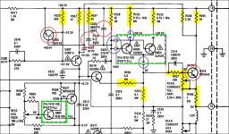
In the pic attached, yellow items have been checked/reflowed, red items have been replaced, and green items have been swapped right to left.
Reflowed all the current-leveling/load resistors on the V+ side of the power amp section (R533, R535, R531). No change.
I replaced Q516 (overcurrent detection) with an MPSA42. No change.
I replaced Q505 (predriver overcurrent negative feedback) with an MPSA92. The output looked good for about 10 seconds (???) then went back to the premature clipping. (The old 2N4125 tested ok in my transistor tester, but what's a good way to more thoroughly test a transistor?)
I checked all the load and biasing resistors attached to the V+ side after the differential amplifier and everything checked out with no significant drift.
So maybe the V+ rail snubber caps went leaky and are mis-biasing the predrivers? I replaced C520 (6.8 nF) and C519 (0.1 uF). No change.
Cleaned with steel wool the screws and pins that tie the power transistors to the rest of the circuit. No change.
Swapped the power transistor assembly (V+ side NPNs Q802, Q804, and cross-over compensation circuit transistor Q801) right channel for left channel. No change.
Since we're clipping at a repeatable, constant voltage instead of seeing a problem that scales with applied voltage, the problem must be a semi-conductor issue (?).
I have not replaced Q507 or Q510. Since they have weird p/ns, I'm not even sure what I'd replace them with...
I have not replaced Q521.
In the pic attached, yellow items have been checked/reflowed, red items have been replaced, and green items have been swapped right to left.
Attachments
Last edited:
More generally, I don't have a good intuition for what mismatched gain in my predriver transistors would look like.
Would this distort my waveform in some telltale way? Cause oscillation? Something else?
I'd love to hear your thoughts, gurus.
Would this distort my waveform in some telltale way? Cause oscillation? Something else?
I'd love to hear your thoughts, gurus.
To review, amp behaves properly with Q516 removed? No abnormal clipping? I could be overlooking something in the narrative.
If the above is correct, I’m to make a very wild guess. You mentioned someone has “worked” on the amp before. I wonder if Q516 might be installed backwards—- I.e. collector and emitter swapped. The transistor will still sort-of work but will have low beta and will have low base-“collector” breakdown behavior.
Trust schematic but ignore ignore any silkscreen. Work from transistor data sheet and visual inspection of board traces when replacing. I.e. don’t mimic previous part orientation, as it may be wrong.
My guess may be wrong but worth a look. Good luck!
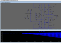
Haven't had a chance to test your guess, but it did get me thinking... I whipped up this LTspice simulation and discovered two possible single-point failures that would cause clipping in simulation resembling my real life problem:
1) an open the trace between the Q802/Q804 collectors and the top of R531 (0.1 ohm resistor that feeds the speaker load).
2) an upside-down/backwards Q510
Item 1 doesn't seem to be the case based on prior investigation. Definitely gonna check out Item 2 tomorrow.
In the attached photo, Q3 is equivalent to a flipped Q10.
Also attached, my LTspice mockup of the 240's predriver/power stage is active diode drop compensator.
Attachments
There is something interestingly odd going on here >If you drive amp without a load, what is max output/clipping behavior?
The amp has separate adjustments for both positive and negative output currents--- eg. R541, Q516. Repeat setup as in first first photo and then tweak R541 to see if output improves.
Good luck.
My M.240 has only two pots. One is quiescent current (both + & -) and the other DC offset. (?)
PS.
For my own information ...
What are todays best replacements for the 5 front-end transistors ???
Last edited:
WOOPS >
I just remembered there are 2 extra pots > being for 'clip level current limiting feedback'.
I just remembered there are 2 extra pots > being for 'clip level current limiting feedback'.
- Home
- Amplifiers
- Solid State
- Marantz 240 premature clipping