Attached is the output stage of a preamp board I'm building and what I measured for the amplifier input stage(don't have schematic). Am I correct to conclude the voltage divider and coupling cap on the output is redundant and can be eliminated?
I'm still populating the preamp so it's easy enough to leave out. I'd like to keep the signal path as simple as possible.
I'm still populating the preamp so it's easy enough to leave out. I'd like to keep the signal path as simple as possible.
Attachments
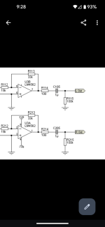
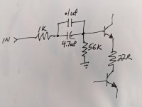
Yes. I assume the first picture is the output schem and the hand drawn second pict is the input. The coupling caps are redundant and one can be eliminated. Both are usually advisable however so that the preamp is compatible with any power amp and plugging and unplugging doesn't cause a big 'click'. Also, I'd make the1uF preamp cap more like 47uF so to be more compatible with the 100 ohm output z. 47uF gives a LF pole at about 6Hz into 600 Ohms.
Yes the first picture is the preamp out and second is the amp input.Both are usually advisable however so that the preamp is compatible with any power amp
These are being mounted in a chassis so the preamp won't be connected to any other amp.
I don't know the input impedance of the amp but I would expect it to be high, much higher than 600 ohms.