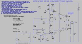
Note that I do not suggest building this due to the fact that it is overly simplistic. Might be good as a mod to a broken existing amp.
This is an untested modification to provide an EF3 output stage for the SWTPC Lil Tiger amp. An emitter follower is also
added in front of the VAS to provide a higher input impedance. Thread on the original design with pictures:
This amp as originally designed failed when driving 4 ohm loads and it is logical to keep the TO-126 transistors as
drivers on board and add much bigger outputs with emitter resistors off board. I'm thinking BD911/912 or TIP35/36
which are all currently available.
Note that this is a single gain stage amp and therefore it should be very stable, but EF3s are known to have local oscillations
so proceed with caution.
Front end transistors are all high voltage to support higher supply voltages.
A goal was to have about 100 mA in the outputs, with enough heat sinking one could go much higher into class A,
also 20 mA in the drivers and 5 mA in the pre-drivers.
Again this is UNTESTED so just a concept.
I found the chassis for my amp but can't find the circuit boards right now, maybe in the future.
The LtSpice file is attached:
Schematic:

This is an untested modification to provide an EF3 output stage for the SWTPC Lil Tiger amp. An emitter follower is also
added in front of the VAS to provide a higher input impedance. Thread on the original design with pictures:
https://www.diyaudio.com/community/threads/swtpc-lil-tiger-amp-18w-spice-simulation.414282/
The closed loop frequency response showed a large peak around 3 MHz so a Cdom cap was added to eliminate it.This amp as originally designed failed when driving 4 ohm loads and it is logical to keep the TO-126 transistors as
drivers on board and add much bigger outputs with emitter resistors off board. I'm thinking BD911/912 or TIP35/36
which are all currently available.
Note that this is a single gain stage amp and therefore it should be very stable, but EF3s are known to have local oscillations
so proceed with caution.
Front end transistors are all high voltage to support higher supply voltages.
A goal was to have about 100 mA in the outputs, with enough heat sinking one could go much higher into class A,
also 20 mA in the drivers and 5 mA in the pre-drivers.
Again this is UNTESTED so just a concept.
I found the chassis for my amp but can't find the circuit boards right now, maybe in the future.
The LtSpice file is attached:
Schematic:

Attachments
Last edited:
Is .1uF enough since it is HF decoupling?
Where do you put the ground end in an amp with split supplies, do you run it back to the PSU caps or?
Rail to rail with split supplies?
Where do you put the ground end in an amp with split supplies, do you run it back to the PSU caps or?
Rail to rail with split supplies?
.1 uF isn’t even close to enough. 47uF was needed on my “KM441”, and usually I just go straight to 100 uF now. Smaller cap like a .01 can be paralleled. With split supplies the cap grounds should connect directly to one another, then to the central ground. Bias circuits should NOT share that ground with the decoupling. Run them separately. Omit the caps, or get the connections wrong, and then go chasing your tail with oscillations (and continue to fear the reaper/EF3). Or you could get very very lucky. I never was. When I started to get religious with the decoupling it was like a miracle occurred.