Hi,
Is the switching noise what makes people not use dc-dc converters in sensible audio circuits such as DACs?
I can't think of a external filter for the output, as the problem is not the ripple but this high frequency switching. 🙁
Many professional audio interfaces use dc-dc converters followed by an LDO. But won't an LDO block these high frequency spikes!? 🤔
Is this the reason that most people on the forum prefer to continue with linear PS?
Attachments
What is wrong with using the recomended Digital Ground and Analogue Grounds that most designers do.
Fitting a low value ceramic capacitor from DG to Ground will block it.
50mV of ripple is of no consequence.
Fitting a low value ceramic capacitor from DG to Ground will block it.
50mV of ripple is of no consequence.
Last edited:
A linear PS fed from mains doesn't suffer from common-mode noise, that might be the reason for preferring it to a mains-fed SMPSU. LDOs sometimes don't have very good PSRR at switching frequencies, though many newer designs do.
In this case it would be high frequency ripple 🙂I can't think of a external filter for the output, as the problem is not the ripple but this high frequency switching.
some dc/dc converters leave out switching cycles at low currents which lowers the ripple frequency. This makes filtering more difficult and may turn out to be audible (because of lower frequency).
Build a common mode filter and you won't see these needles anymore.I can't think of a external filter for the output, as the problem is not the ripple but this high frequency switching.
Linear PSU's with capacitive input filter generates large amounts of line harmonics, much more difficult to elliminate than higher frequencies ones.
A good SMPS with a well designed PFC will do better than a linear counterpart.
In the other hand are lots of well designed line filters boxed in metallic cases. But be carefull with filters: all of them need a proper load impedance, as it is well known in Filters Theory. Otherwise, the filter may make problems worse.
sensible audio circuits such as DACs?
50mV of ripple is of no consequence.
In this case it would be high frequency ripple 🙂
some dc/dc converters leave out switching cycles at low currents which lowers the ripple frequency. This makes filtering more difficult and may turn out to be audible (because of lower frequency).
If it ends up on the reference supply, a couple of dozens of microvolts at almost any ultrasonic frequency that isn't an exact multiple of the sample rate suffices to spoil the performance of high-performance sigma-delta DACs. That's because a DAC multiplies its digital input signal with its reference, and in a sigma-delta DAC, that digital signal contains loads of ultrasonic shaped quantization noise. Multiplying that with a ripple of about the same frequency may convert it to audio frequencies, much like the frequency conversion in the mixer stage of a radio.
That doesn't look like power supply ripple ...Many professional audio interfaces use dc-dc converters followed by an LDO. But won't an LDO block these high frequency spikes!? 🤔
However, the success of the LDO method depends on whether the SMPS switching frequency is within the control bandwidth of the LDO. Regulators like 7805 do not have such bandwidth and entirely depend on the output capacitor to reduce impedance at high frequencies. LDOs with decent loop gain at switching frequency would definitely do much better.
I have used SMPS for DACs but as Marcel says above, the reference voltage needs to be clean and is often obtained using a CCS / shunt regulator.
Last edited:
It's not ripple, it's the switching noise that passes to the output.That doesn't look like power supply ripple ...
The question is: How to filter the output switching noise? 🤔
yep. Pulse Skip Mode (PSM) increases the frequency according to the current, but i'm using PWM mode which keeps the frequency fixed (500Khz) even at low load.some dc/dc converters leave out switching cycles at low currents which lowers the ripple frequency. This makes filtering more difficult and may turn out to be audible (because of lower frequency).
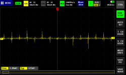
If you pay attention to the image, the spikes appear every 2uS, but their frequency must be much higher, and this is my difficulty in filtering.
I tried with common and differential mode, but it always passes as if there was nothing. 🙁Build a common mode filter and you won't see these needles anymore.
You expected anything that deviated from DC to be removed by the LDO, didn't you ? That was what I was answered to. Post regulator LDOs are primarily used to cut ripple.It's not ripple, it's the switching noise that passes to the output.
Switching noise is usually suppressed (not filtered) by adding snubbers across the switching components as required.The question is: How to filter the output switching noise? I tried with common and differential mode, but it always passes as if there was nothing.
It could also originate from saturation of the filter inductor.If you pay attention to the image, the spikes appear every 2uS ...
Can you please provide some explanation /more details here...?? How large is the "large amounts"? Large with reference to what? What frequency spectrum are you talking about? Is this "large amounts of line harmonics" an issue for the mains supply (240 for example), or an issue for the regulated DC rail side of things..?? Thanks.Linear PSU's with capacitive input filter generates large amounts of line harmonics, much more difficult to elliminate than higher frequencies ones.
Several reasons, commercial offering work to different economics than DIY. For a commercial product, designing a SMPS that works with the product is expensive but can be written off over a large volume. An SMPS is mostly lighter and smaller so when you have to ship thousands all over the world that can make a difference. And you can have a SMPS that can work with any input voltage and frequency wherever in the world, something a DIY doesn't need to be concerned about. Also things like power factor correction is easier with a SMPS and you need that these days for certification.Hi,
Is the switching noise what makes people not use dc-dc converters in sensible audio circuits such as DACs?
I can't think of a external filter for the output, as the problem is not the ripple but this high frequency switching. 🙁
Many professional audio interfaces use dc-dc converters followed by an LDO. But won't an LDO block these high frequency spikes!? 🤔
Is this the reason that most people on the forum prefer to continue with linear PS?
Now having LDO's after an SMPS can serve many goals. It can give you more voltages, these days chips often use several voltages. It can provide isolation, filtering, less noise.
For DIY this all plays less except when you need more voltages.
It is more than extraordinary explained in most of the great books about electronics from rhe 40's to today. I'll try mine: when a full wave rectifier feeds a capacitor and a load, the cap is charged a top of Vpeak or 1.414 times RMS value. The diode (Tube, silicon, germanium, selenium, copper oxide or whatever you want) stops to conduct when source voltage (supposed sinus wave) decreases. Thus, current flows in diodes and transformers during short periods of time, tipically under 10% of an hemicycle. Current is a succesion of peaks or very large current in short periods of time. This wave contains large amounts of harmonics, mainly 3rd. It may be lightly alleviated by inductances is this circuits but never elliminated.Can you please provide some explanation /more details here...?
As you can see, PFC's are designed to avoid such problem usually with power factors of 0.995 or better and very low THD on line currents.

I agree, but these "problems" will have more impact on the mains supply and external devices, this is a certification issue.Current is a succesion of peaks or very large current in short periods of time. This wave contains large amounts of harmonics, mainly 3rd. It may be lightly alleviated by inductances is this circuits but never elliminated.
On the power supply side of the device, the issue with the linear PS is low efficiency and high ripple, BUT...
from what i have observed, dealing with these switching noises can be much more difficult to deal with than a simple 120Hz ripple from a bridge rectifier. 😕
Gosh, working those skills of cutting the original question, and then explaining the obvious, and the non-applicable, aren't you?
The PFC is used to correct the constant lag between current and voltage, in AC circuits.
The linear power supplies and their OUTPUT can be squeaky clean, their output impedance can be very low, and completely uniform across a vast frequency range, ensuring instant current response at all (including the high switching) requirements of digital circuitry - like when processing high sample rates (1.536MHz). There is no comparison between a properly designed liner regulation, and an SMPS (not to mention a DC-DC converter).
The question here is how to remove the switching rubbish, as produced by SMPS and DC-DC converters. The answer is - not possible. The noise that everyone's saying can be "filtered" (poof....magic!), has to be either dumped to the low impedance ground (such ground does not exist in SMPS design), burnt in the form of heat, or tuned into/dissipated as a magnetic field.
It is more than extraordinary explained in most of the great books about electronics from rhe 40's to today. I'll try mine: when a full wave rectifier feeds a capacitor and a load, the cap is charged a top of Vpeak or 1.414 times RMS value. The diode (Tube, silicon, germanium, selenium, copper oxide or whatever you want) stops to conduct when source voltage (supposed sinus wave) decreases. Thus, current flows in diodes and transformers during short periods of time, tipically under 10% of an hemicycle. Current is a succesion of peaks or very large current in short periods of time. This wave contains large amounts of harmonics, mainly 3rd. It may be lightly alleviated by inductances is this circuits but never elliminated.
As you can see, PFC's are designed to avoid such problem usually with power factors of 0.995 or better and very low THD on line currents.
The PFC is used to correct the constant lag between current and voltage, in AC circuits.
The linear power supplies and their OUTPUT can be squeaky clean, their output impedance can be very low, and completely uniform across a vast frequency range, ensuring instant current response at all (including the high switching) requirements of digital circuitry - like when processing high sample rates (1.536MHz). There is no comparison between a properly designed liner regulation, and an SMPS (not to mention a DC-DC converter).
The question here is how to remove the switching rubbish, as produced by SMPS and DC-DC converters. The answer is - not possible. The noise that everyone's saying can be "filtered" (poof....magic!), has to be either dumped to the low impedance ground (such ground does not exist in SMPS design), burnt in the form of heat, or tuned into/dissipated as a magnetic field.
Last edited:
I agree, but these "problems" will have more impact on the mains supply and external devices, this is a certification issue.
On the power supply side of the device, the issue with the linear PS is low efficiency and high ripple, BUT...
from what i have observed, dealing with these switching noises can be much more difficult to deal with than a simple 120Hz ripple from a bridge rectifier. 😕
Have a look here:
https://www.diyaudio.com/community/threads/post-you-smps-noise-spectrum-measurements.394518/
Thank you very much for your explanation! 👍The PFC is used to correct the constant lag between current and voltage, in AC circuits.
The linear power supplies and their OUTPUT can be squeaky clean, their output impedance can be very low, and completely uniform across a vast frequency range, ensuring instant current response at all (including the high switching) requirements of digital circuitry - like when processing high sample rates (1.536MHz). There is no comparison between a properly designed liner regulation, and a SMPS (not to mention DC-DC converter).
The question here is how to remove the switching rubbish, as produced by SMPS and DC-DC converters. The answer is - not possible. That noise that everyone's saying can be "filtered" (poof....magic!), has to be either dumped to the low impedance ground (such ground does not exist in SMPS design), or burnt in the form of heat.
Unless you have a very bad designed audio chain and/or you have an abnormally good ear and/or you listen AM stations like me, it happens that radiated 100 or 120Hz and higher order are audible, whilst 100KHz of a normal SMPS with or not with PFC incorporated, aren't. So I still prefeer the SMPS over the linear one, except you are using choke input filter after rectification.
I understand your thinking.Unless you have a very bad designed audio chain and/or you have an abnormally good ear and/or you listen AM stations like me, it happens that radiated 100 or 120Hz and higher order are audible, whilst 100KHz of a normal SMPS with or not with PFC incorporated, aren't. So I still prefeer the SMPS over the linear one, except you are using choke input filter after rectification.
I agree that the problems generated with 100hz/120hz are audible, not at 100khz... but, not directly.
When injecting a 100khz signal along with the audible signal, you will not hear the 100khz directly, but it will certainly "disturb" the semiconductor that is receiving this signal.
Correct me if I'm wrong.
There's a DIY kit in the Store (here is a link) which may be of interest. The Forum discussion thread about this kit calls it "an inline DC filter for SMPS wall warts." Absolute maximum ratings are 3A and 48V.
Quite a few testimonials from delighted builders are sprinkled throughout the discussion thread. They talk about listening impressions with, and without, the DC filter installed. Some kit builders put it in a little "dongle" chassis with a female input jack and male output plug, so the filter can be quickly inserted and removed without opening the audio equipment's chassis. Image below.

Quite a few testimonials from delighted builders are sprinkled throughout the discussion thread. They talk about listening impressions with, and without, the DC filter installed. Some kit builders put it in a little "dongle" chassis with a female input jack and male output plug, so the filter can be quickly inserted and removed without opening the audio equipment's chassis. Image below.
- Home
- Amplifiers
- Power Supplies
- Switching Noise DC-DC Converter