I'm quite experienced in electronics but this is my first audio amp of this type with quasi MOSFET output.
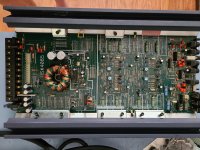
I am repairing a US Acoustics - USX-4085 amplifier I bought not working.
Says "USX4085 REV C silk" on the board. (It does not have the blue light bar)
The unit powered up with red protect LED lit.
I found two output IRF540A MOSFETs (Q213 and Q214) on channel 2 shorted.
I tested the remaining components in channel 2 comparing to good channels and all measured OK.
I removed the two output MOSFETs, clamped it back in the heat sink, and now the amp powers up with green LED and no red protect LED lit.
Main amp rails measure +25.5V and -25.4V and preamp rails measure +15.5V and -15.4V.
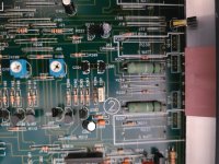
Thermal camera shows these components much warmer than the rest:
Q105, Q205, Q305, Q405 (Looks like maybe lower MOSFET driver?)
OPT1 (Looks like it gates the bias, perhaps muting?)
R29, R30 (Pre amp power supply)
R31 (Power supply primary snubber)
Questions:
1) I can't seem to be able to find the IRF540A as it's been discontinued an so far everyone shows no stock. IRF540PBF looks close but not sure. IRF540Z doesn't look like a good match. I'm unsure what the critical parameters are for a MOSFET in this application. Any other alternates which would work?
2) How do I set bias after replacing the MOSFETs and to check the good channels?
3) Anyone have a schematic for this amp?
4) Any other tests I should perform? ( New to car amps but have scopes, 6 digit dmm, HV diff probes, arb signal generator, etc. in my lab)
Thank you in advance for any help,
Rich
I am repairing a US Acoustics - USX-4085 amplifier I bought not working.
Says "USX4085 REV C silk" on the board. (It does not have the blue light bar)
The unit powered up with red protect LED lit.
I found two output IRF540A MOSFETs (Q213 and Q214) on channel 2 shorted.
I tested the remaining components in channel 2 comparing to good channels and all measured OK.
I removed the two output MOSFETs, clamped it back in the heat sink, and now the amp powers up with green LED and no red protect LED lit.
Main amp rails measure +25.5V and -25.4V and preamp rails measure +15.5V and -15.4V.
Thermal camera shows these components much warmer than the rest:
Q105, Q205, Q305, Q405 (Looks like maybe lower MOSFET driver?)
OPT1 (Looks like it gates the bias, perhaps muting?)
R29, R30 (Pre amp power supply)
R31 (Power supply primary snubber)
Questions:
1) I can't seem to be able to find the IRF540A as it's been discontinued an so far everyone shows no stock. IRF540PBF looks close but not sure. IRF540Z doesn't look like a good match. I'm unsure what the critical parameters are for a MOSFET in this application. Any other alternates which would work?
2) How do I set bias after replacing the MOSFETs and to check the good channels?
3) Anyone have a schematic for this amp?
4) Any other tests I should perform? ( New to car amps but have scopes, 6 digit dmm, HV diff probes, arb signal generator, etc. in my lab)
Thank you in advance for any help,
Rich
Attachments
1) PBF is an acronym for Pb (lead, plumb) Free. Use them without any warn.
4) Replace all components before the blown MOSFET's. Including small resistor. After a catastrofic failure, some components may look good but are damnified inside.
Once repairing an AT PC PSU, it started working OK under no load. Loading it, the PSU drops its voltage. To be short: a 1N4148 in one of the bases of 2SC3039 had 0.7V in both directions!
The 540a has long been discontinued. The PBF should be OK.
Do you have a 12v power supply with an amp meter?
Do you have a 12v power supply with an amp meter?
I have power supplies with meters.The 540a has long been discontinued. The PBF should be OK.
Do you have a 12v power supply with an amp meter?
With the two bad MOSFETs out, it draws about 0.68A at 12.6V.
Clamp all semiconductors tightly to the heatsink.
Confirm that rotating the bias pots clockwise causes an increase in current draw.
I assume that you replaced all know defective parts.
Since the originals aren't available, I'd pull the outputs from a different channel and confirm that the blown channel now works. If it does but the new replacement parts do not, you know that there is an incompatibility. I don't suspect that there will be a problem but it's always possible.
To set the bias, start with the bias control at the minimum and rotate until you just see a slight increase in idle current.
Sweep the entire audio spectrum with an output of about 1v AC at the speaker terminals. Load the amp. 4 ohms would be a good place to start. If there is no crossover distortion at the upper end of the spectrum, the bias is sufficient. If there is distortion, increase the bias slightly. If it takes more than about 1/4 amp of increase in bias and there is still distortion, check the other channels. All channels should bias the same.
Install the replacement FETs and adjust the bias the same way and confirm that the biasing requirements are the same for that channel, as well.
Appreciate the suggestions.
I swapped the MOSFETs from a good channel in and it works so it looks like I was lucky it was just the two outputs crowbaring the rails.
I checked each channel and the bias adjusts the same on each channel like described above.
The crossover distortion disappears just a little before the current starts to go up.
I'll order the new 844-IRF540PBF MOSFETs from Mouser.
I also looked at the power supply rail noise to see if the capacitors were OK.
Nope, there is 500mV high frequency ripple with positive being twice as bad as negative.
I'll have to order them as well.
Current values are 2200uF/35V Chemi-con marked SMS.
I'm currently looking at Mouser part 667-EEU-FR1V222B as a possibility.
Any suggestions for good replacements?
That should be fine. Did you pull the caps and check them for value?
Caps can fail but it's relatively rare, especially the secondary filter caps.
Pull and check the rectifiers to confirm that you don't have an open diode in one of them.
Caps can fail but it's relatively rare, especially the secondary filter caps.
Pull and check the rectifiers to confirm that you don't have an open diode in one of them.
If the amp is for your own use, I suggest to use Nichicon brown series. 105°C and low ESR. Also add smaler caps paralleled toguether to decrease the ripple: 2200//100//22//1uF. This way the higher frequency ripple is managed by lower value units with higher resonant frequency.
My parts came in today so I'll try to work on it this weekend unless life gets in the way.
In the mean time, because it was bothering me that I didn't have a schematic and US Acoustics was crickets, I created my own.
Feel free to give it out to anyone trying to repair one of these.
Beware that I likely made some mistakes so any feedback is welcome.
It's in KiCAD so it's easy to edit.
It's an interesting design.
Attachments
You may be the first person to ever produce the diagram for an entire amp on this forum in the 20+ years that I've been here.
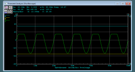
The bias setup looks like an MTX and if so, low bias means an asymmetrical clipping of the output waveform. If you see something like the attached diagram, the bias needs to be set slightly higher.
The bias setup looks like an MTX and if so, low bias means an asymmetrical clipping of the output waveform. If you see something like the attached diagram, the bias needs to be set slightly higher.
Attachments
Been a while but I wanted to give an update on this.
The IRF540PBF replacements worked perfectly.
I also chased a whole lot of fractured solder joints causing intermittent problems.
I found the two power supply 2200uF/35V capacitors were out of tolerance (about 30-40% low capacitance) so I replaced them with 667-EEU-FR1V222B which worked perfectly.
Found the RCA jacks were broken and had intermittent connections to the RA tips so I replaced them with panel mounted.
Pots were dirty and noisy so I used deoxit which solved that.
Push button switches were broken so I replaced them with E-Switch PBH2UEESNPNARBLK, Mouser part#: 612-PBH2UEESNPNARBLK.
Finally after all that it works VERY well.
It's such a fantastic warm sounding amp with lots of power.
I found another USX2050 and fixed it also.
It has a similar circuit.
I found it had failed power supply MOSFETs which I replaced with same type.
Pots needed cleaning with deoxit which worked.
Found some fractured solder joints.
Works good now.
The biasing was as described by Perry.
Beware that it's touchy and will draw a lot of current really quick so be ready to back off quickly.
I used a variable power supply at 14V with a 2A current limit and analog meter so it was easy to see when the current started jumping up.
Attached is a schematic of the USX2050 in case anyone needs it.
Same conditions apply.
Rich
Attachments
For future reference:
Simply adding new solder to solder connections with cracked connections isn't always reliable. There is a layer of oxidation that doesn't always float out of the connection. Add new solder and then desolder completely. If the lead is bent-over, straighten it in the through-hole and resolder the connection.
Simply adding new solder to solder connections with cracked connections isn't always reliable. There is a layer of oxidation that doesn't always float out of the connection. Add new solder and then desolder completely. If the lead is bent-over, straighten it in the through-hole and resolder the connection.
I concur. I had to de-solder lots of solder joints with the Edsyn Soldapullt then re-solder them. Many hours.
That's probably nice but more than I could ever justify (or afford). The DS017 is a very good option, for others reading this.
- Home
- General Interest
- Car Audio
- US Acoustics - USX-4085 Repair