Hello,
I do have some speakers I play with. The Crossovers are outside, same channel from the amp, speaker switch.
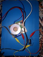
Main capacitors, 3.3uF (second order) are on the board, additional/bypass capacitors are connected via alligator/wires clips.
Does the length of wires affect the influence of the smaller capacitors to the main ones?
(Longer travel, slow speed of the electrones, late arrival at the main capacitor)
Practically, adding parallel capacitor upto 50% value of the main cap does not produce noticeable sound changes.
It seems to me, in cases the capacitors are soldered, the sound changes (as to be expected). Or it is result of imagination.
Thx
I do have some speakers I play with. The Crossovers are outside, same channel from the amp, speaker switch.
Main capacitors, 3.3uF (second order) are on the board, additional/bypass capacitors are connected via alligator/wires clips.
Does the length of wires affect the influence of the smaller capacitors to the main ones?
(Longer travel, slow speed of the electrones, late arrival at the main capacitor)
Practically, adding parallel capacitor upto 50% value of the main cap does not produce noticeable sound changes.
It seems to me, in cases the capacitors are soldered, the sound changes (as to be expected). Or it is result of imagination.
Thx
Excessive capacitor lead length adds inductance and picks up noise, even from other parts in the crossover. It's best to minimize this.
You are most likely experiencing expectation bias and easily fooled human senses...that's how magicians make a living. And if you do the math, the velocity of a signal in a wire (barring external influences) is about 70 - 80%-ish of the speed of light, any propagation delays will be irrelevant in conductors that short. A far greater effect will be the resistance, and stay reactance of the wire. The resistance of the wire should be accounted for in the design, and any stray reactance can be generally ignored in a passive crossover as long as the conductors aren't excessively long, say less than 30 cm or so.
Mike
Mike

To a high degree of accuracy, at audio frequencies the full physics description reduces to lumped parameters like R, L, and C. A rough, general estimate of lead inductance would be 10nH per cm.
Any delay in linear audio circuitry is mostly related to bandwidth. In the region where the frequency response is relatively flat, the phase shift will be small and quasi-linear. And the derivative of linear phase shift is the definition of a time delay.
Any delay in linear audio circuitry is mostly related to bandwidth. In the region where the frequency response is relatively flat, the phase shift will be small and quasi-linear. And the derivative of linear phase shift is the definition of a time delay.
That what I was afraid of. The wires look like 24-26 AWG or thiner , choking of the signal through the parallel caps? Latency or/and weak signal that does not affect the main caps?Any delay in linear audio circuitry is mostly related to bandwidth
Hmm, "Drift velocity, the average speed at which electrons travel in a conductor when subjected to an electric field, is about 1mm per second".is about 70 - 80%-ish of the speed of light
You would not even look at mine ugly creations, but I'll try.Can you post some photos?
Hmm, "Drift velocity, the average speed at which electrons travel in a conductor when subjected to an electric field, is about 1mm per second".
Also true, but the EM propagation velocity is also that of the signal.
I do worry as well, as they are ferromagnetic and else.
What would you suggest a proper test / flexible environment should look like?
What would you suggest a proper test / flexible environment should look like?
The clips are surely steel and the contacts are dubious as well.
Keep power resistors well separated and raised off the board, to avoid excessive heating.
I tend to tack solder parts for testing that will not be permanent. That also makes them reusable.
You don't have to cut the lead off, just solder at the ends.
Keep power resistors well separated and raised off the board, to avoid excessive heating.
I tend to tack solder parts for testing that will not be permanent. That also makes them reusable.
You don't have to cut the lead off, just solder at the ends.
contact resistance of these shabby alligator clips may amount to several ohms -
thus confirming your observations in posting #1 -
but with a more basic explanation
thus confirming your observations in posting #1 -
but with a more basic explanation
sorry, do not know these at all. And I am not a "cap expert" knowing all series from all brands.
Not the same thing.Hmm, "Drift velocity, the average speed at which electrons travel in a conductor when subjected to an electric field, is about 1mm per second".
- Home
- Loudspeakers
- Multi-Way
- Capacitor wire length for tests