...or 'The Dual Mono ACA Mini Turbo' to be precise.
It's no secret that I am a huge fan of the ACA Mini for many reasons.
It sounds a lot better than you'd expect, it's loud enough for 95% of my needs, and it's power-consumption is low for a real class A power amp, just to mention a few.
Unfortunately I also happen to own some low impedance speakers, AND I have a need for total control of the low end of the frequency range.
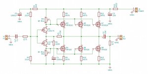
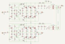
So, a little while back I posted this schematic and asked the question:
'Would it be possible to build a turbo-edition of the ACA-Mini and perhaps get a small increase in DF?'
Fortunately Papa said 'Do it!' (or close), so I set out to build a Mini Turbo, and this is how it went down.
It's no secret that I am a huge fan of the ACA Mini for many reasons.
It sounds a lot better than you'd expect, it's loud enough for 95% of my needs, and it's power-consumption is low for a real class A power amp, just to mention a few.
Unfortunately I also happen to own some low impedance speakers, AND I have a need for total control of the low end of the frequency range.
So, a little while back I posted this schematic and asked the question:
'Would it be possible to build a turbo-edition of the ACA-Mini and perhaps get a small increase in DF?'
Fortunately Papa said 'Do it!' (or close), so I set out to build a Mini Turbo, and this is how it went down.
Attachments

I already decided on the chassis before i started on the board layout.
I have previously used a taller version of this for my ACA (with premium components), and I loved the quality.
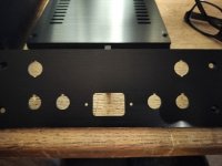
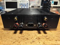
The rear was pre-drilled, and took very little work to finish. Unfortunately it was not made for my preferred fused IEC-plug.
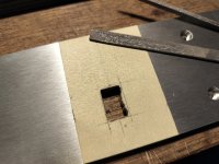
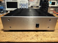
As with 'all' the previous amps I've build, I have to have my beloved square toggle-power-switch. I just have to!
Only problem is the fact that there are very few things I hate more in this world, than to make the #%&@&£# square holes in the front.
It takes AGES, and my hands are broken for days.
... but I have to.
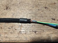
Mains cable is shielded, because it makes sense, it looks good, I sleep better, and beause ZM says 'do it'!
I have previously used a taller version of this for my ACA (with premium components), and I loved the quality.
The rear was pre-drilled, and took very little work to finish. Unfortunately it was not made for my preferred fused IEC-plug.
As with 'all' the previous amps I've build, I have to have my beloved square toggle-power-switch. I just have to!
Only problem is the fact that there are very few things I hate more in this world, than to make the #%&@&£# square holes in the front.
It takes AGES, and my hands are broken for days.
... but I have to.
Mains cable is shielded, because it makes sense, it looks good, I sleep better, and beause ZM says 'do it'!
Attachments


All internals arrived quickly from Mouser and Digitech. Only the ClarityCaps had to be sourced elsewhere.
Chassis, feet and terminals I got off eBay.
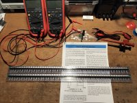
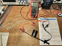
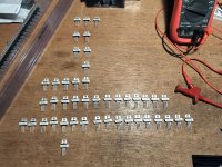
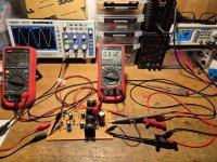
The fact that I would have to do some FET-matching myself, to be able to build this, was actually the bit that scared me the most.
I've always had a feeling that there was an element of woodoo to this task, and that everything would explode if I would ever try it myself,
but... nothing did, and I actually ended up finding it both relaxing and rewarding.
I did try it without the sink. Won't recommend it though. No damage, but it is almost impossible to get a stable reading.
It says 'Ease of Paralelling' in the Vishay datasheet. I believe this is true.
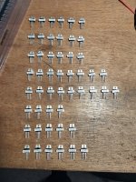
I ordered 50 of each, hoping it would be enough to find a couple of triplets.
It turned out I could have made several octets of both types, matched to 3rd digit.
Chassis, feet and terminals I got off eBay.
The fact that I would have to do some FET-matching myself, to be able to build this, was actually the bit that scared me the most.
I've always had a feeling that there was an element of woodoo to this task, and that everything would explode if I would ever try it myself,
but... nothing did, and I actually ended up finding it both relaxing and rewarding.
I did try it without the sink. Won't recommend it though. No damage, but it is almost impossible to get a stable reading.
It says 'Ease of Paralelling' in the Vishay datasheet. I believe this is true.
I ordered 50 of each, hoping it would be enough to find a couple of triplets.
It turned out I could have made several octets of both types, matched to 3rd digit.
Attachments
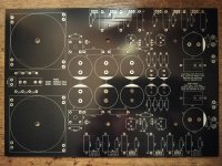
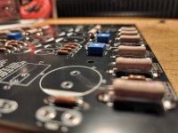
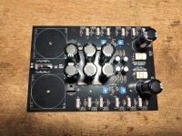
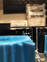
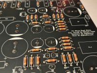
Boards from JLCPCB, 'black edition'. Fell in love with the colour when I built my WHAMMY.
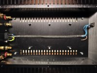
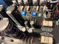
Nothing special populating these. Resistors first, transformers last.
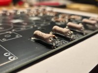
One thing I did that might be total overkill though:
When it came down to mounting the FET's, I started out by mounting the board in the chassis and the FET's on the sink.
I then lightly 'tacked' one leg on each FET with solder (pic: pop_5), removed the board and FET's from the chassis and then soldered all FET's properly.
This way there will be less stress on the solder/FET's when tightening it all down, ...I think.
Note: Pictures in this and later posts, are of the final version/build. There are no pictures of my f**k-ups.
Nothing special populating these. Resistors first, transformers last.
One thing I did that might be total overkill though:
When it came down to mounting the FET's, I started out by mounting the board in the chassis and the FET's on the sink.
I then lightly 'tacked' one leg on each FET with solder (pic: pop_5), removed the board and FET's from the chassis and then soldered all FET's properly.
This way there will be less stress on the solder/FET's when tightening it all down, ...I think.
Note: Pictures in this and later posts, are of the final version/build. There are no pictures of my f**k-ups.
Attachments
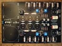

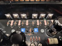
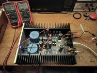
This was supposed to be the easy part, but this is actually where everything started to go wrong.
Measuring VB and VO as you're supposed to while adjusting, I noticed that even with the pots at 12 o'clock, VB remained at 0VDC, ...until it didn't.
Passing 12 o'clock on the pots, VB suddenly jumped to 300mV, and a very audible hum appeared from the transformers.
I switched it off, dialed the bias back, and started over, but this time with a speaker connected.
As soon as I switched it on, I realized that I had actually built an oscillator.
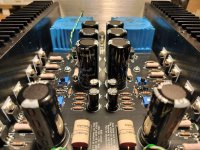
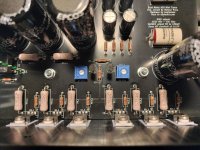
Having zero faith in my skills, I started over. Made a new and completely different layout and ordered some new boards.
Moved all components from the old board, connected a speaker, powered up the amp and voila, one more oscillator up and running.
Feeling pretty dissapointed with my progress at this point, I slouched down in front of the TV, and happened to stumble on a show about paracites.
And this was when I remembered that zomeone once said: Unless you know exactly what you're doing, use gate-stoppers.
As I know abolutely not what I'm doing... I started over again. Made a new schematic, this time with gate-stoppers.
New layout, new boards, moved all components once more, connected a speaker, powered up the amp and... total silence!
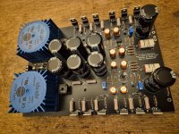
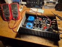
Started the bias-procedure, and this time, it behaved exactly as expected.
Left it to cook, readjusting a few times over a couple of hours.
Temp at hottest spot on the sinks measured ambient + 14 degrees C.
Zero mechanical hum/noise from the actual amp. Zero hum/noise from the speakers. Zero thump/noise when switching it on and off.
Measuring VB and VO as you're supposed to while adjusting, I noticed that even with the pots at 12 o'clock, VB remained at 0VDC, ...until it didn't.
Passing 12 o'clock on the pots, VB suddenly jumped to 300mV, and a very audible hum appeared from the transformers.
I switched it off, dialed the bias back, and started over, but this time with a speaker connected.
As soon as I switched it on, I realized that I had actually built an oscillator.
Having zero faith in my skills, I started over. Made a new and completely different layout and ordered some new boards.
Moved all components from the old board, connected a speaker, powered up the amp and voila, one more oscillator up and running.
Feeling pretty dissapointed with my progress at this point, I slouched down in front of the TV, and happened to stumble on a show about paracites.
And this was when I remembered that zomeone once said: Unless you know exactly what you're doing, use gate-stoppers.
As I know abolutely not what I'm doing... I started over again. Made a new schematic, this time with gate-stoppers.
New layout, new boards, moved all components once more, connected a speaker, powered up the amp and... total silence!
Started the bias-procedure, and this time, it behaved exactly as expected.
Left it to cook, readjusting a few times over a couple of hours.
Temp at hottest spot on the sinks measured ambient + 14 degrees C.
Zero mechanical hum/noise from the actual amp. Zero hum/noise from the speakers. Zero thump/noise when switching it on and off.
Attachments
Time for some music.
Part of my feeble mind was kind of hoping for an amp that would sound like the regular Mini, with just a little more grip.
It didn't take too much listening to figure it was not quite that.
I have of course read all papa's descriptions of his FirstWatt amps, and based on this alone, I think this one might actually sound more like a micro-F5 than a Mini. Please note, I have never heard an F5 ...yet!?
I mean, there are many similarities to the Mini, but Initially it seems more 'in your face' than the original. Fuller. Ritcher. More ...colour.
It seems to give me details that I have never noticed before with any other amp. Unfortunately this is not without it's problems either.
Quite a few of my favourite albums are not as pleasurable to listen to anymore.
This is most noticeable on compressed material. Music that used to sound just like that, compressed, lacking dynamic information, suddenly sounds like the amp is playing all the information that was lost in the mix. Especially digitally compressed material can sound really gritty with this one.
I still like it though. It does have the xtra grip I was looking for, and It has a very seductive way with well produced material.
It colours in a way that make me believe it is the most revealing amp in the world, and this automatically makes me focus on other parts of my musical collection, but as much as I like this one, it isn't exactly what I was looking for when I started building, and there really is only one solution for this very 'problem'...
I have to build one more amp.
Just one more!
Attachments
A few final thoughts:
I know some of you are looking for measurements, but all my lab-gear is of the well known brand POS, so unfortunately I have nothing useful to show.
I found that changing the value of the gate-stoppers had quite a big impact on the 'colour'.
I started out with 47ohm, but it actually sounded like the amp was clipping when pushed, or forced into some sort of oscillation.
100ohm was a lot better but it was still too gritty somehow, so I ended up with 150ohm.
Going even bigger had very little (if any) effect.
Changing the feedback resistor even a tiny bit, also had a big impact on sound.
I ended up with 500ohm instead of the original 475ohm, but this was purely a matter of taste.
I liked the little bit of softness it added, but my audio-geek-friend preferred the original 475ohm.
Going lower seems to make it more sharp/gritty in a way that I don't like, but again, thats just me.
So... even though I didn't quite hit home with this one, it has still been a great learning-experience to build it.
This site contains all the information you need to be able to build exacly what you want.
It also contains access to a massive amount of brainthrust.
The more you read and the more questions you ask, the bigger the odds of reaching your goal.
I cannot thank ya'll enough for sharing your knowledge and experience. Thank you!!!
I'll be back!
PS: If you are looking for a really great 5W class-A poweramp... build the original ACA Mini!
Attachments

Nice work! Thanks for sharing. BTW, do you have updated schematics including the power supply? Thanks!
Last edited:
Maybe you need to try a single ended;-)
More important than the distinction between class A or A/B is the distinction between SE, PP, complementary transistors PP. Because: identical parts sound different. dissimilar parts, like complementary transistors, sound more different. Ergo: The two half-waves of PP amplifiers sound different.
A tip, also as proof: connect the channel-separated power supplies.
Oops... forgot the final schematic.
@cumbb: I have actually built a few SE amps over time, and there is definately a lot to like about 'em, but I really am a PP guy at heart.
It was a Stasis amp that lit the fire for me back in the day. Very PP!
@cumbb: I have actually built a few SE amps over time, and there is definately a lot to like about 'em, but I really am a PP guy at heart.
It was a Stasis amp that lit the fire for me back in the day. Very PP!
Attachments


The FETs actually have a positive tempco. The 0.75 Ohm source resistors are the negative tempco devices that prevent thermal runaway.
Wired resistors usually has positive tempcos. As the wire heats up, its lenght increases and the diammeter decreases. So I don't see any kind of compensation.
In the other hand, you must ensure that temperature compensation is fufficiently fast as to prevent entire device destruction.
In the other hand, you must ensure that temperature compensation is fufficiently fast as to prevent entire device destruction.
Part2: The MicroF4, (or the BabyBuffer)
So, what I learned from building the TurboMini was that 3 pairs of 520/9520's was enough to give me the low-end-grip I was looking for.
I also learned that paralleling output-critters in common-source can have a noticeable impact on the sonic footprint.
Searching for a way to proceed with this in mind, somehow it seamed like the easiest solution to just skip the gain and change everything to common-drain.
Looking at this change in the schematic, I couldn't help but notice some similarities with the F4, and as this happens to be my favourite amp ...in the world... why not try and add the rest of the magic from the F4 and see what you get.
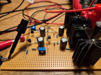
At this point I actually sat down and tried to work out some math behind the circuit.
I even read the full TL431 datasheet and every single formula in it, at which point my brain exploded.
Calculating stuff in analog circuits with more than 3 components is just beyond my paygrade. Or maybe I'm just to old. Sorry.
Found a piece of perfboard instead and after a little experimenting (yes, you can kill a TL431), it actually ended up working as intended.
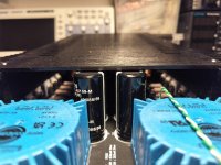
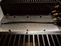
Laid out and ordered a new board to fit the existing holes in the case.
Removing the old board from the case, I noticed an interesting dust-pattern. It appears there is quite a significant airflow.

So, what I learned from building the TurboMini was that 3 pairs of 520/9520's was enough to give me the low-end-grip I was looking for.
I also learned that paralleling output-critters in common-source can have a noticeable impact on the sonic footprint.
Searching for a way to proceed with this in mind, somehow it seamed like the easiest solution to just skip the gain and change everything to common-drain.
Looking at this change in the schematic, I couldn't help but notice some similarities with the F4, and as this happens to be my favourite amp ...in the world... why not try and add the rest of the magic from the F4 and see what you get.
At this point I actually sat down and tried to work out some math behind the circuit.
I even read the full TL431 datasheet and every single formula in it, at which point my brain exploded.
Calculating stuff in analog circuits with more than 3 components is just beyond my paygrade. Or maybe I'm just to old. Sorry.
Found a piece of perfboard instead and after a little experimenting (yes, you can kill a TL431), it actually ended up working as intended.
Laid out and ordered a new board to fit the existing holes in the case.
Removing the old board from the case, I noticed an interesting dust-pattern. It appears there is quite a significant airflow.
Attachments
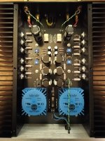
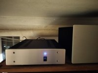
Well here it is, and this one is a keeper!
No stability or biasing issues. Bias set to 130mV across the source-resistors. Temperature stable at ambient + 14C
This is not an F4, but the sonic footprint is surprisingly close. At least close enough to make me smile, big.
The Baby does seem to have a tiny bit more 'fill' in the low end, and a little less transparancy, but we are talking very small differences.
I know from experimenting with the Mini, that a different output cap can have a serious impact, and perhaps using Harris-critters could bring it even closer to the original, but for now my foot is tapping, no matter what kind of music I play, and that's as good as it gets to me!
Once again, thank you all for your help and inspiration.
Attachments

- Home
- Amplifiers
- Pass Labs
- Mini Turbo