Hi all.
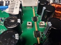
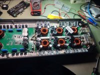
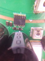
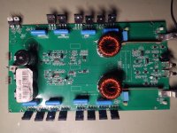
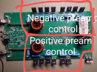
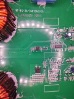
I have a Banda Viking 15.000 which doesn't power ON at all. If anyone have some idea where the softs start receiving power. Also if the preamplifier board on the left is dependent by amplifier board from right side. In a photo attached is a photo with the joint between the 2 boards.
I have a Banda Viking 15.000 which doesn't power ON at all. If anyone have some idea where the softs start receiving power. Also if the preamplifier board on the left is dependent by amplifier board from right side. In a photo attached is a photo with the joint between the 2 boards.
Attachments
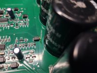
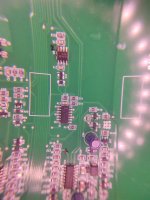
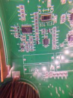
I attached photos with all components from soft star area + gain/balance + pream control section.
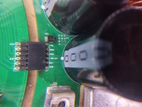
The MCU is MSP430F21
The MCU is MSP430F21
Attachments
-
 IMG_20240528_054530555_HDR.jpg326.4 KB · Views: 43
 -
 IMG_20240528_054547466.jpg352.9 KB · Views: 46
 -
 IMG_20240528_054224577.jpg279 KB · Views: 42
 -
 IMG_20240528_054103746.jpg334.4 KB · Views: 46
 -
 IMG_20240528_054035952.jpg427.2 KB · Views: 55
 -
 IMG_20240528_054027453.jpg421.1 KB · Views: 51
 -
 IMG_20240528_054017397.jpg363.9 KB · Views: 48
 -
 IMG_20240528_053824079.jpg493.6 KB · Views: 38
 -
 IMG_20240528_054002269.jpg383 KB · Views: 41
 -
 IMG_20240528_053903838.jpg519.5 KB · Views: 49
 -
 IMG_20240528_053734562.jpg470.7 KB · Views: 44
 -
 IMG_20240528_053646205.jpg489.2 KB · Views: 58
 -
 IMG_20240528_053353748.jpg540.5 KB · Views: 48
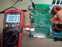

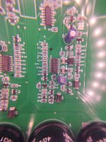
U9 Receives 0.37V and emit 0.37V.
But Vin is terminal 8 which goes to U3 next to MCU.
Vin terminal 8 is marked with red marker in previous photos.
Maybe the datasheet is wrong. Usually terminal 1 is Vin most of the time and last terminals are outputs.
Vout terminal 1 goes/comes from U11.
But Vin is terminal 8 which goes to U3 next to MCU.
Vin terminal 8 is marked with red marker in previous photos.
Maybe the datasheet is wrong. Usually terminal 1 is Vin most of the time and last terminals are outputs.
Vout terminal 1 goes/comes from U11.
Attachments
I will measure. But Is no voltage anywhere around that components. And I see all iC and MCU doesn't receive voltage. Is like no power to all of them.
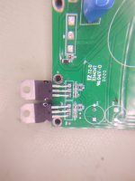
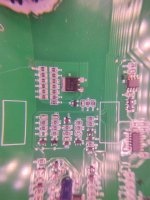
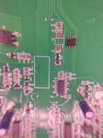
Only U7 from photo attached, have 12V at pin no 15,16, 17. But U14 doesn't.
In rest only some diodes and resistors gets 12V.
Some resistors have 12V in one end and other end have 6 vold. I desoldered few resistors.. measure and they are in right value.. For some resistors with the same value, the 12 volt goes through, but for some doesn't. Is strange.
I desoldered and measure some diodes too. SMD transistors too. All are ok.
Somehow the control area doesn't receive power.
I will keep checking when I get home. Maybe is something wrong on the other board of the amplifier which communicate with the main one.
Attachments

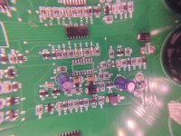
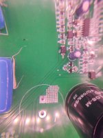
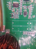
For example this resistors are 330k and receives 12V from North side. One was interrupted and some was under valued. I replaced them temporary but still doesn't go through 12Vol.. Is just 1.60V at the other end. And after the 12V goes through 2 resistors, results in that common 0.37V which is all over the board 🤔.
Attachments

In the Brazilian amps and clones, there seem to be a lot of 4.7 and 10 ohm resistors that open or go out of tolerance. Good if you've checked them and confirmed that they're within tolerance.
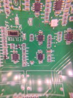
U7 has only 16 pins.
The voltage for the MCU may have to pass through multiple components....
A switching transistor or regulator controlled by the remote turn-on voltage
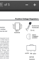
A pre-regulator (the 7805?)
A 3.3v regulator (the LP2985)
Keep following the circuit back from the supply terminal of the 7805 and R116 towards the remote turn-on input.
U7 has only 16 pins.
The voltage for the MCU may have to pass through multiple components....
A switching transistor or regulator controlled by the remote turn-on voltage
A pre-regulator (the 7805?)
A 3.3v regulator (the LP2985)
Keep following the circuit back from the supply terminal of the 7805 and R116 towards the remote turn-on input.
- Home
- General Interest
- Car Audio
- Banda Viking 15,000 no power ON