Hi
Does anyone have a diagram for this amplifier?
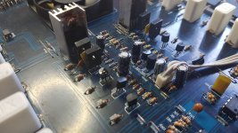
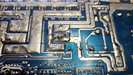
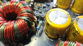
The problem with this amplifier was that it consumed a very large current, but only when the speaker was connected. The section controlling the power transistors was responsible for this. After opening the housing, I noticed two badly burned resistors right next to the transformers.
It's probably an RC filter between the transformer and the double diodes.
By default, there were 4k7 1W and a 1nF capacitor, I changed R to 4k7 2W, but they still reach 120oC after a few minutes. The amplifier plays, theoretically everything is OK, but the resistors...
Does anyone have a diagram for this amplifier?
The problem with this amplifier was that it consumed a very large current, but only when the speaker was connected. The section controlling the power transistors was responsible for this. After opening the housing, I noticed two badly burned resistors right next to the transformers.
It's probably an RC filter between the transformer and the double diodes.
By default, there were 4k7 1W and a 1nF capacitor, I changed R to 4k7 2W, but they still reach 120oC after a few minutes. The amplifier plays, theoretically everything is OK, but the resistors...
Attachments
Last edited:
Those resistors will run hot but will run hotter than they should if the power supply has a problem causing excessive ringing, if the values of the components were poorly chosen or if the capacitor is out of tolerance.
That RC circuit is referred to as a 'snubber'.
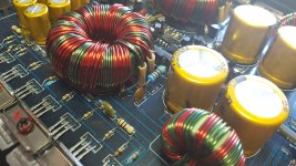
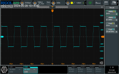
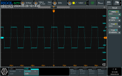
What do the waveforms on the secondary windings look like?
Is the capacitor within tolerance? It appears to be discolored.
As a side note, if you want the degree symbol:
(hold) ALT0176 release ALT = ° 120°C
That RC circuit is referred to as a 'snubber'.
What do the waveforms on the secondary windings look like?
Is the capacitor within tolerance? It appears to be discolored.
As a side note, if you want the degree symbol:
(hold) ALT0176 release ALT = ° 120°C

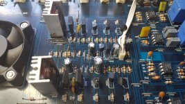
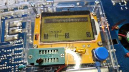
I hope you have seen that one A1015 is fried. I have the diagram somewhere, i need to get back to you these days.
I saw damaged transistors in the control stage, I replaced them and it works now.
I provide details in the attachments. I saw somewhere on the forum that I'm not the only one who has a problem with excessive heating of the 4k7 resistors.
The capacitors seem to be OK, but maybe their parameters change when the resistors heat them.
I provide details in the attachments. I saw somewhere on the forum that I'm not the only one who has a problem with excessive heating of the 4k7 resistors.
The capacitors seem to be OK, but maybe their parameters change when the resistors heat them.
Attachments
It's OK for a resistor to run hot.
At 120°C, it's probably down to about 40% of it's rated power. You could look up the datasheet for the replacement resistors you used to see their derating curve.
The discoloration is mainly due to the paint coating. A ceramic coated resistor wouldn't discolor as quickly.
Some of the crunch amps use an 8.2 k resistor.
Are those waveforms with the snubbers in the circuit, or with them out of the circuit?
The oscilloscope measurement was made with a snubber in the circuit.
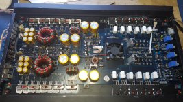
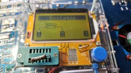
The factory resistors don't look good.
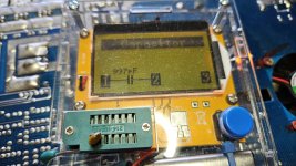
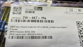
I put the ones with a tolerance of 1% metal film (photo), because that's what I had on hand, but I think I'll order the following:
https://www.tme.com/um/en/details/rox2sj4k7/tht-resistors/te-connectivity/5-1625890-4/
These resistors have an operating temperature range of -55...155°C
The factory resistors don't look good.
I put the ones with a tolerance of 1% metal film (photo), because that's what I had on hand, but I think I'll order the following:
https://www.tme.com/um/en/details/rox2sj4k7/tht-resistors/te-connectivity/5-1625890-4/
These resistors have an operating temperature range of -55...155°C
Attachments
Last edited:
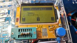
They should be replaced but are just barely out of tolerance.
Look at wirewound resistors as well.
The capacitors are cheap. Replace them as well. If you use a much higher voltage cap, it will be larger and will run cooler (more surface area). You could even lay it down on the board with some heatsink compound and that would pull some heat out of it.
There are a lot of options but there's no reason to overthink it.
- Home
- General Interest
- Car Audio
- Crunch GP 1500.1 hot 120oC resistors