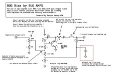
I am in my way of designing my singled ended amplifier and come across the topic of blocking distortion. I am in search of the way to mitigate the problem and meet BUGBIAS from YouTube and Facebook. This circuit is proposed by BUG AMP in 2020. If anyone has tried the circuit or would like to make some comment, please share your view on it. Thanks.
Attachments

The simplest method to prevent blocking distortion during high volume music to the RC coupling network . . .
Turn the Volume Control Down.
That will keep grid current from charging the capacitor that is part of the RC network.
All other schemes that prevent blocking distortion is called . . . Compression.
That reduces the dynamic range of the music.
Joseph Haydn's Surprise Symphony would not be able to wake up those sleepers at the finale of his symphony.
If you need more power to make your listening more pleasurable, build or purchase an amplifier with 3 dB to 10dB more power.
10dB more power sounds like 2X as loud.
The reason . . . ears respond Logarithmically.
As the sound level increases, the muscles and bones in our ears move, which decreases the mechanical advantage from the eardrum to the cochlea.
Automatic Volume control, so to speak.
As to the schematic in Post # 1, I do not see any documentation on how and where to connect the bug circuit to or between two stages that use RC coupling.
Have Fun designing and building your single ended amplifier!
Please let us know what tubes and circuits you are going to use.
By the way, push pull amplifiers that use RC coupling can also suffer from blocking distortion.
Again, turn the volume down; or get an amplifier with 3dB to 10dB more power; or purchase a compressor.
"There is hardly anything relatively simple which works very well . . . that can not be modified to be made much more complex".
If any one is interested on how it works you may watch the video starting from 27:30. The author also demo the effectiveness of his circuit in the later part if the video.
januaryabc,
Thanks!
Nice Video explanation.
Push Pull, Class AB1:
At 25:32 and on, it does mention the cutoff of one tube.
And of course, the other tube cuts off when the signal goes in the other direction.
That is all according to Class AB1, by definition.
Works good.
It does reduce or eliminate any crossover distortion that would otherwise be caused by blocking from the (2) RC couplings (push and pull RCs);
But the signal is still being clipped during loud music passages (compresses the signal).
At some point of overload, it is necessary to turn the volume down, get a more powerful amplifier, or get more efficient loudspeakers.
I do not like the sound of crossover distortion.
And, I do not like the sound of clipping, or even soft clipping (that is called Compression).
Single ended is different, but fortunately the Bug Bias will prevent the RC from blocking the signal;
But single ended has only one phase of output tube(s) [SE and PSE]; unlike push pull.
Class A1 definition requires that for single ended the tube(s) do not cut off.
Single ended Class A1, if the tube cuts off, it is no longer Class A1.
Repeat: If the SE tube(s) cuts off, turn the volume down; or get a more powerful amplifier, or get more efficient loudspeakers.
No single bias correction scheme can solve all bias problems, or other power limitation problems.
Just my opinions.
Last edited:
There was the Carver solution, which was based on a video baseline restorer. The grid starts conducting current at some positive signal voltage through the grid resistance, so a reverse diode and series resistor gets added, that is arranged to conduct the opposite current, at the opposite equal negative voltage. A positive offset voltage, from the signal, is needed to do that at the diode, so it conducts at the proper neg. signal voltage. Equal, opposite currents keep the coupling capacitor at zero avg, volts (ideally). Could use a 6AL5 to get a matching diode.
Last edited:
After searching for Carver solution, I meet another old post talking about dc restorer circuit.
https://www.diyaudio.com/community/threads/putting-stock-in-carver.239652/
It seems that the simple circuit should be effective in limiting the negative swing to 2x of bias level. My purpose is to prevent the single ended amp from suffering from a short duration of complete cutoff after large transient signal of low enough frequency.
Attachments
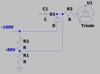
This circuit looks like standard one that is used in fuel injection where you want to clamp and conduct away the flyback spike every time the fuel injectors close, so it's not a new concept. With that, you set a fixed clamp voltage where you want to clip, but here you have a potential divider to fine tune that voltage.
An alternative to just turning the amplifier down is to alter the previous stage to produce a little less gain (and perhaps then, if possible, do the opposite for the distorting stage).
kind regards
Marek
An alternative to just turning the amplifier down is to alter the previous stage to produce a little less gain (and perhaps then, if possible, do the opposite for the distorting stage).
kind regards
Marek
That circuit looks complicated. There are other ways to reduce or potentially eliminate blocking distortion. I recommend reading Sy's article about the RLD and how the LED bias scheme more or less eliminated it. There are of course circuits that can replace the LEDs if so desired. One of those ways is with a TL431 and a BJT PNP power transistor, more or less as described in the TL431 spec sheet. I've done it and it works quite well.
Here is a link to the RLD article:
https://www.syclotron.com/the-red-light-district/
Here is a link to the RLD article:
https://www.syclotron.com/the-red-light-district/
simple grid choke for fast restore?After searching for Carver solution, I meet another old post talking about dc restorer circuit.
https://www.diyaudio.com/community/threads/putting-stock-in-carver.239652/
It seems that the simple circuit should be effective in limiting the negative swing to 2x of bias level. My purpose is to prevent the single ended amp from suffering from a short duration of complete cutoff after large transient signal of low enough frequency.
Or just use a drive circuit that can deliver some positive current like a Cathode , MOSFET, BJT or whatever you like follower.
I have used both a cathode followers and MOSFET followers and both can work nicely.
Instead of clipping and blocking right away the amp goes A2 or AB2 and then you get some extra power output for your extra parts.
Yep the distortion in A2 or AB2 mode tends higher but sure is a lot lower than clipping and blocking distortion.
MOSFETs if used in this application are best selected for very low capacitance.
Cathode follower tubes need a decent ability to deliver current.
Yes if you keep driving it harder the output tubes will then clip but still no blocking if there is some headroom in the driver follower circuit.
If the output tubes are pentodes some sort of screen power limiter is a good idea so the output tubes do not melt the screens if the volume keeps getting turned up more still.
I find insuring the driver circuit can deliver some current a win win. A bit more power and better overload recovery.
I have been using a simple mosfet follower to drive the grid of an output tube including DHT's. The coupling cap sees a resistive load of several hundred K ohms regardless of grid current flow, so it has a constant state of charge under all listening conditions. The circuit can be seen here in the Tubelab TSE-II amp and remains unchanged since the initial design over 20 years ago. It just works.
Attachments
Norman Koren used the same approach in his "The Emperor's New Amplifier" dating back to 1997. He used a cathode follower instead of a MOSFET follower, however. Here is a link describing that amplifier in detail.
https://www.normankoren.com/Audio/TENA.html
https://www.normankoren.com/Audio/TENA.html
Hi Januaryabc. Thanks for having a look at my circuit. I think a lot of the comments in this thread are high quality. For example the closest analog to my circuit is Bob Carvers circuit that of course predates my own. Also his is for a SE application too! I developed my circuit before I was aware of his and I feel mine is sufficiently different to merit it’s own designation, being for fixed bias and Push Pull applications.I am in my way of designing my singled ended amplifier and come across the topic of blocking distortion. I am in search of the way to mitigate the problem and meet BUGBIAS from YouTube and Facebook. This circuit is proposed by BUG AMP in 2020. If anyone has tried the circuit or would like to make some comment, please share your view on it. Thanks.
There are of course loads of ways of eliminating blocking. Direct coupling a follower, transformer coupling or grid choke are some examples. My solution is somewhat unique in that it does exactly nothing to the circuit unless the output stage is clipped. So it doesn’t add anything to the signal path, for whatever that’s worth to a designer. My solution is also easily disabled for AB comparisons.
If you haven’t already have a look at this quick demonstration where I compare the same circuit with and without Bug Bias enabled.
Good luck with your project!
- Home
- Amplifiers
- Tubes / Valves
- "BUGBIAS" circuit to solve blocking distortion for capacitor coupled tube amplifier