Up to now, I always had single primary power transformer, thus I am a little discomorted.
Here’s this little xformer, dual primaries, where the dots are on the outer pins.
To make it a 230V transformer, I bridge the outer Pin (dot) with the inner pin (no dot) of the other primary, correct?
Is there a method to measure/test it without connecting it?
Thank you all!
Here’s this little xformer, dual primaries, where the dots are on the outer pins.
To make it a 230V transformer, I bridge the outer Pin (dot) with the inner pin (no dot) of the other primary, correct?
Is there a method to measure/test it without connecting it?
Thank you all!
Attachments
Easy, use a low wattage bulb (DBT) in the primary as you test it. If you get it wrong the bulb will light and the secondaries will have no voltage.
The pin configuration looks a bit unusual as you would expect the inner pins to join, however the dots clearly show not to do it that way.
So use a bulb and be sure.
The pin configuration looks a bit unusual as you would expect the inner pins to join, however the dots clearly show not to do it that way.
So use a bulb and be sure.

He's asking without connecting anything, so how's a bulb helping with that?
I would recommend a multimeter or a oscilloscope (scope on the secondary only please).
Unfortunately there is no way of figuring this out without connecting anything.
That being said, if you just keep consistent with connecting the dots the way you want it, it should be fine.
If the DC resistance isn't to low, you probably can also hook it up to an audio amplifier and use a sine wave.
Or when the resistance is rather low, use a resistor in series with it so you won't damage the amplifier.
Downside is that voltage drops.
He's asking without connecting anything, so how's a bulb helping with that?
I took it to read that he didn't want to connect it, get it wrong and then have bad things happen 🙂
You can sit and look at it all day but in the end you have to power it up and check for real.
I suppose myleftear was intending "without connecting it to mains"?
You could connect the primary windings in different configutations to an amp playing a low voltage 50 Hz sine wave. Measure the secondary outputs to know the correct connection.
Edit: or measure primary impedance of connected coils. Higher impedance is the correct connection.
Edit2: just saw b_force was quicker ...
This only doesn't tell us anything about polarity 😉 🙂Edit: or measure primary impedance of connected coils. Higher impedance is the correct connection.
Well the CE mark is definitely fake, so perhaps don't use it and live a long life...Up to now, I always had single primary power transformer, thus I am a little discomorted.
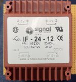
Here’s this little xformer, dual primaries, where the dots are on the outer pins.
To make it a 230V transformer, I bridge the outer Pin (dot) with the inner pin (no dot) of the other primary, correct?
Is there a method to measure/test it without connecting it?
Thank you all!
For safe testing, you can power it with a low voltage filament transformer or an old AC wall-wort. Say something with a 6 to 20 Volt output.
Then multiply the output readings by the ratio.
Then multiply the output readings by the ratio.
How can you see the pins? 😉The pin configuration looks a bit unusual as you would expect the inner pins to join, however the dots clearly show not to do it that way.
@myleftear - Start with the datasheet... Attached. Key information pasted below for your reference.
Even with the wonky CE mark... if you got it from a reputable source... I wouldn't give it a second thought.
Attachments
Yes, got them from mouser. I'll look at it (not into it 😉 ) tomorrow. (While waiting for the final parts to continue on the holygrail)
Sorry - quickly deleted a post b/c I had a brain fade while looking at an Antek transformer and a Talema. LOL! Apologies. So, for those that get e-mail notifications with a snippet, ignore. 🙂
^ As Mooly surmised, you would not connect the middle pins (2 and 4). You'd likely connect 2 and 3 (or 4 and 1). The datasheet matches the diagram on the transformer, which is good. I was curious.
^ As Mooly surmised, you would not connect the middle pins (2 and 4). You'd likely connect 2 and 3 (or 4 and 1). The datasheet matches the diagram on the transformer, which is good. I was curious.
- Home
- Design & Build
- Construction Tips
- Dual primaries to 230V: the dot