I have an Ion Obelisk which as a fault where the output is lower on one side, I've checked the psu voltage to the poweramp which +60v however the voltage on the positive side of C1 is 21v on one side ( which if im reading the schematic correctly is correct) and only 9v on the other.
Any pointers on where to look?

Any pointers on where to look?
Hi,
Do you mean C1's positive terminal in the other channel is 9V?
Key voltages that will reveal the amp's voltage bias are noted in the rectangular boxes, i.e. +28.5V at the emitters of TR6/ TR7, +23V at emitter of emitter of TR1, and 22.5V at base of TR1. (These all interact, but base of TR1 will typically be about 0.6V lower than its emitter.)
Would you report what voltages you observe at these three points? The voltage drop across R28 is also of interest, but please don't try to adjust until we know more about what's wrong.
Remember that voltages in the working channel can be a guide to nominal voltages in the problem channel.
Thanks!

Both voltages are low I think, perhaps some capacitor is leaking to ground? C1 maybe? Or the bias setting resistors have changed (R4/6/7/8)? Might be something else too. Worth checking Vbe is sensible for all the transistors when powered up (around 0.6V), be very careful not to short things taking those measurements though...
Hi,
Do you mean C1's positive terminal in the other channel is 9V?
Key voltages that will reveal the amp's voltage bias are noted in the rectangular boxes, i.e. +28.5V at the emitters of TR6/ TR7, +23V at emitter of emitter of TR1, and 22.5V at base of TR1. (These all interact, but base of TR1 will typically be about 0.6V lower than its emitter.)
Would you report what voltages you observe at these three points? The voltage drop across R28 is also of interest, but please don't try to adjust until we know more about what's wrong.
Remember that voltages in the working channel can be a guide to nominal voltages in the problem channel.
Thanks!
Thanks
I found a broken solder joint on C1 fixed that and voltages are as follows, A denotes other channel, amp was on a dim bulb limiter incase of slip ups
C1 / C1A - 21.6vdc
Tr1 / Tr1A Base - 21.6vdc
Tr1 / Tr1A Emitter - 22vdc
Tr6 / Tr7 - Emitters - 27.5vdc
Tr6a / Tr7a Emitters - 27.7vdc
One channel output still much lower than the other 4v AC vs 0.5v AC measured at speaker terminals
The noted DC voltages may be slightly low, but not by much.
I'm not sure what you're telling me. Is the 0.5v AC indicating low audio gain? Please clarify what your measuring and how.
If the signal gain is low, inspect the R9 and C5 path for possible failed parts or faulty soldering or PCB traces. R9 and R10 set the signal gain at about 1+R10/R9. i.e. about 38 V/V or about 31.6dB. Of course, failed C1 or C18 could also give low output.
One channel output still much lower than the other 4v AC vs 0.5v AC measured at speaker terminals
I'm not sure what you're telling me. Is the 0.5v AC indicating low audio gain? Please clarify what your measuring and how.
If the signal gain is low, inspect the R9 and C5 path for possible failed parts or faulty soldering or PCB traces. R9 and R10 set the signal gain at about 1+R10/R9. i.e. about 38 V/V or about 31.6dB. Of course, failed C1 or C18 could also give low output.
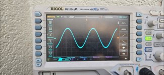
Here's the output wave on a scope first left channel second the right channel which is the low output one.


Attachments
Last edited:
To check that the pre amp part to the circuit is working correctly where best to scope? Looking at the schematic shouldnI expect 10v out from it?

Looks like 5x attenuation, ie -14dB or so, with no gross signal distortion.
Can you compare levels at 100Hz and 10kHz too, see if the attentuation is frequency-dependent?
Can you compare levels at 100Hz and 10kHz too, see if the attentuation is frequency-dependent?
I'd suspect that C5 has gone open circuit in the weak channel perhaps, dropping the gain across the board?
If I understand, the problem remains in the PA and is unchanged.
Try the following, using x10 probes: Note AC amplitude at generator output, and compare at C2, base TR1, emitter TR1. There should be very little change in AC amplitude at any of these three points. Measure directly on the R9 resistor lead that connects to C5: you should see same DC voltage as emitter of TR1, but there should be no AC signal present since it should be shorted to ground through C5.
Assuming results are as described and that there is clean sine wave with correct bias (about 28.5VDC) at the amp output, the problem would appear to be defective resistance value at R9 or R10.
Good luck.
- Home
- Amplifiers
- Solid State
- Ion Obelisk 2 help