Hi diyers,
I would like to submit this project for a mid-bass transmission line to you. I kindly ask for your help in identifying any errors or improvements.
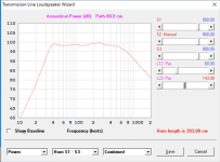
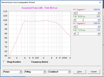
The desired result was approximately 40-500hz bandwidth and the woofer selected was the Volt RV3143.
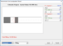
I tried to model the line with the Hornresp SW, these are the parameters used:
I attach some screenshots, and thanks in advance for any help.
I would like to submit this project for a mid-bass transmission line to you. I kindly ask for your help in identifying any errors or improvements.
The desired result was approximately 40-500hz bandwidth and the woofer selected was the Volt RV3143.
I tried to model the line with the Hornresp SW, these are the parameters used:
- TL section: 800cm^2
- TL length: 203cm
- speaker offset: 60cm
- section filling: 60% short part, 10% long part
I attach some screenshots, and thanks in advance for any help.
Attachments

For the construction I had thought of something like this, you can see an attached drawing.
I have some doubts about the point where the woofer is located, let me explain better, from the point of view of the offset it is exactly where calculated with hornresp, but I have doubts whether some unwanted resonances could be created due to the particular "exposure" of the 2/3 woofer in the open chamber to 1/3 in the closed chamber.
Thanks again for any support.
Last edited by a moderator:
A bit of interesting reading, if you have not already gone through those threads.
https://www.diyaudio.com/community/threads/an-improved-transmission-line-alignment.243483/
https://www.diyaudio.com/community/threads/an-improved-transmission-alignment-ii.391041/
https://www.diyaudio.com/community/threads/an-improved-transmission-line-alignment.243483/
https://www.diyaudio.com/community/threads/an-improved-transmission-alignment-ii.391041/
Note that the deflector in the upper right corner is counter -productive.
Driver offset is important, it needs precise modeling, but given you have a straight line a Zd of a third the line length is very close.
dave
Driver offset is important, it needs precise modeling, but given you have a straight line a Zd of a third the line length is very close.
dave
Last edited:
Consider that the box only loads the driver to its upper mass corner (Fhm) where T/S theory peters out:I have some doubts about the point where the woofer is located, let me explain better, from the point of view of the offset it is exactly where calculated with hornresp, but I have doubts whether some unwanted resonances could be created due to the particular "exposure" of the 2/3 woofer in the open chamber to 1/3 in the closed chamber.
Fhm/Hz = 2*Fs/Qts'
34400 cm/4/Fhm = 1/4 WL, so huge compared to the pipe's dimensions, ergo just needs some damping material for nearby reflections.
(Qts'): (Qts) + any added series resistance (Rs)
Thanks to everyone for the precious advices.
Shouldn't the section be kept constant when changing the direction of the TL?
If I didn't misunderstand, the speaker offset might be fine? and the particular position shouldn't be a problem, just some damping material for nearby reflections.
Can I ask you why it is counterproductive?Note that the deflector in the upper right corner is counter -productive.
Driver offset is important, it needs precise modeling, but given you have a straight line a Zd of a third the line length is very close.
dave
Shouldn't the section be kept constant when changing the direction of the TL?
If I didn't misunderstand, the speaker offset might be fine? and the particular position shouldn't be a problem, just some damping material for nearby reflections.
Can I ask you why it is counterproductive?
Shouldn't the section be kept constant when changing the direction of the TL?
A properly designed TL is a low pass filter so that only the fundemental gets out the terminus.
The increase in cross-section at a bend acts as a low pass filter and means less damping can be used and you can preserve more of the fundemental.
dave
- Home
- Loudspeakers
- Multi-Way
- Mid-Bass TL