Hello,
I just purchased a Harmon Kardon FX30X tube receiver and I'm trying to find some information on this thing. I found a schematic for the FX3000 receiver because I read that my model, (FX30X), is the kit version of the FX3000...I hope that's true! I'm wondering if the FX30X was a kit perhaps there is a build manual floating around out there. That would be invaluable in restoring this thing! The problem is that other than the schematic, there appears to be absolutely nothing on the web about my receiver. I hope I am wrong! If anyone has a link or info I would greatly appreciate it!
Thank you
In the first post, the site's admin claims to have what you need:
https://vintagetubeelectronics.com/harman-kardon-fa30xk-receiver/
Hugo
https://vintagetubeelectronics.com/harman-kardon-fa30xk-receiver/
Hugo

Thanks huggygood,
That makes sense and its a great idea! I don't understand why documentation is so scarce for the FA-30X so I'll take your advice.
That makes sense and its a great idea! I don't understand why documentation is so scarce for the FA-30X so I'll take your advice.
Hello All, I just received some replacement electrolytic caps and I don't understand why someone appears to have replaced a 3900 ohm resistor with a 62000 ohm value on the C60 electrolytic cap?? (See the attached pictures). I'm trying to decide if I should follow the schematic or just keep what I have. Now I have the Harmon-Kardon FA-30X and this schematic is for the FA-3000X but I couldn't find a FA-30X schematic. My gut tells me to follow the schematic and use a variac but my gut is wrong about 80% of the time! Any advice would be appreciated!!!
Thanks for reading this.
Thanks for reading this.
Attachments


I don't understand why someone appears to have replaced a 3900 ohm resistor with a 62000 ohm value on the C60 electrolytic cap.
That's the power supply for the phono stage. Either resistor would work, but use whatever gets you to the phono plate DC voltages on the schematic.
Thanks Directdriver, I now feel confident that I have the correct schematic! Thanks you for the information!
Hello All,
I was hoping to get some advice on a couple of things I noticed in the restoration of my FX30X receiver....
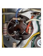
I just replaced the electrolytic's and I powered the unit up and was able to get pretty good FM reception. All in all the amp sounded pretty good. I just happened to place my hand across the metal cases of the electrolytic caps and I got a little shock. Every other device I've re-capped usually has the cap shells grounded to the chassis but this receiver doesn't the caps are mounted onto an insulator. A twist tab on the cap is connected to a what I believe is a grounding wire, (see attached image). Is this normal to get a lift off of the cap cans? The AC cord for this receiver is just a 2 prong cord with no ground...
Also, I stupidly wiped away the lettering on the FM dial. I was stunned that the lettering was so flimsy. Does anyone have a recommendation on where I can get a decal or rub on transfer of the lettering I destroyed?
Finally, I've been studying possible ways I can remove the glass to clean it and apply new FM dial graphics. Aside from dynamite I don't see any way to remove the glass, ...without destroying it that is. I'm sure someone has done it but I just don't see how it can be done. It is held in place with some metal clips that don't want to let go!
Thanks for reading this and for any advice you might have!
I was hoping to get some advice on a couple of things I noticed in the restoration of my FX30X receiver....
I just replaced the electrolytic's and I powered the unit up and was able to get pretty good FM reception. All in all the amp sounded pretty good. I just happened to place my hand across the metal cases of the electrolytic caps and I got a little shock. Every other device I've re-capped usually has the cap shells grounded to the chassis but this receiver doesn't the caps are mounted onto an insulator. A twist tab on the cap is connected to a what I believe is a grounding wire, (see attached image). Is this normal to get a lift off of the cap cans? The AC cord for this receiver is just a 2 prong cord with no ground...
Also, I stupidly wiped away the lettering on the FM dial. I was stunned that the lettering was so flimsy. Does anyone have a recommendation on where I can get a decal or rub on transfer of the lettering I destroyed?
Finally, I've been studying possible ways I can remove the glass to clean it and apply new FM dial graphics. Aside from dynamite I don't see any way to remove the glass, ...without destroying it that is. I'm sure someone has done it but I just don't see how it can be done. It is held in place with some metal clips that don't want to let go!
Thanks for reading this and for any advice you might have!
Attachments
The glass was installed, so it can be removed. You won't have to break anything. The clips are welded before the glass is installed.
It probably slides in from the top. Just post some good close photos of the edges of the glass from the rear.
It probably slides in from the top. Just post some good close photos of the edges of the glass from the rear.
Hello All,
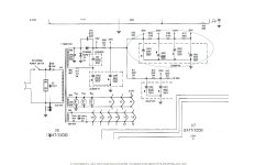
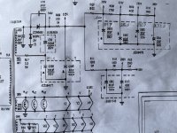
I replaced all the power supply electrolytics in my Harmon-Kardon FA-30X. I bought this thing on ebay so there have probably been half a dozen people fiddling with it in it's lifetime. For example, in the attachment titled "C60 (copy).jpg" there is a mysterious 62K ohm resistor circled that is not on the schematic. I put it back to a 3900 ohm resistor but I noticed that after playing the receiver for about an hour the power transformer was hot to the touch. Today, I powered it up to take some voltage measurements, (see attachment "schematic02.jpg").
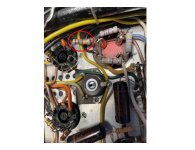
One thing I did different this time was that I left out all the tubes for the FM section of the receiver. I was curious if any of the resistors around the power supply electrolytic caps were hot. Oh yes! The circled resistor in the attachment "C60_07062024_02.jpg" was very hot to the touch! Also, I am wondering if it is a different value from the schematic? If I read the schematic correctly it should be 1500 ohms. In attachment "C60_07062024_02.jpg", the circled resistor is 2700 ohms?
I find schematics mystifying and perhaps I could be mistaken, either way I think the circled resistor in attachment "C60_07062024_02.jpg" is way hotter than it should be.
Thank you all for reading this!
I replaced all the power supply electrolytics in my Harmon-Kardon FA-30X. I bought this thing on ebay so there have probably been half a dozen people fiddling with it in it's lifetime. For example, in the attachment titled "C60 (copy).jpg" there is a mysterious 62K ohm resistor circled that is not on the schematic. I put it back to a 3900 ohm resistor but I noticed that after playing the receiver for about an hour the power transformer was hot to the touch. Today, I powered it up to take some voltage measurements, (see attachment "schematic02.jpg").
One thing I did different this time was that I left out all the tubes for the FM section of the receiver. I was curious if any of the resistors around the power supply electrolytic caps were hot. Oh yes! The circled resistor in the attachment "C60_07062024_02.jpg" was very hot to the touch! Also, I am wondering if it is a different value from the schematic? If I read the schematic correctly it should be 1500 ohms. In attachment "C60_07062024_02.jpg", the circled resistor is 2700 ohms?
I find schematics mystifying and perhaps I could be mistaken, either way I think the circled resistor in attachment "C60_07062024_02.jpg" is way hotter than it should be.
Thank you all for reading this!
Attachments

Sorry but I don't understand anything.
Let's move forward step by step.
To begin with, what is your mains voltage? (from your wall outlet) because it seems that all the voltages are too high and in the same proportions except B+4 which is a problem which will be seen later.
As a point of reference, see if you have 6.3Vac on V2/3/4.
Let's move forward step by step.
To begin with, what is your mains voltage? (from your wall outlet) because it seems that all the voltages are too high and in the same proportions except B+4 which is a problem which will be seen later.
As a point of reference, see if you have 6.3Vac on V2/3/4.
- Home
- Amplifiers
- Tubes / Valves
- Harmon Kardon FA30X