Good day folks,
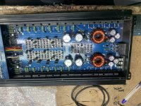
I got a BMF600.4 in, unit appears to be in original condition. It came in reportdly becoming distorted.
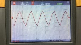
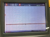
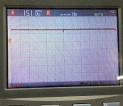
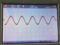
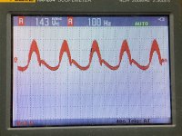
Powers up and verified the unit passes a clean 100hz sine wave on all four channels, however at 10khz, only the front right channel passes a clean sine wave, the other three channels pass a somewhat sawtooth/triangle wave.
When I go lower with the freq all four channels pass clean sine waves. I have clean sine waves leaving the pre/xo section entering the differential pairs.
Anyone ever came across a similar problem as this?
I got a BMF600.4 in, unit appears to be in original condition. It came in reportdly becoming distorted.
Powers up and verified the unit passes a clean 100hz sine wave on all four channels, however at 10khz, only the front right channel passes a clean sine wave, the other three channels pass a somewhat sawtooth/triangle wave.
When I go lower with the freq all four channels pass clean sine waves. I have clean sine waves leaving the pre/xo section entering the differential pairs.
Anyone ever came across a similar problem as this?
Attachments
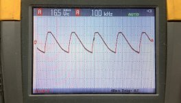
There’s no change in waveform, on one of the three channels there’s very very little rounding of the waveform, I’d say negligible.
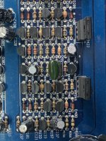
The differential transistors are responsible for error correction. I think I'd move those 4 transistors from the good channel to one of the other channels to see if they will make a difference.
This assumes that you are 100% sure that the signal is clean going into the diff amp.
Are the regulated voltages (±15v) as they should be?
Does heating or cooling the differential amp transistors make a difference?
This assumes that you are 100% sure that the signal is clean going into the diff amp.
Are the regulated voltages (±15v) as they should be?
Does heating or cooling the differential amp transistors make a difference?
The differential transistors are responsible for error correction. I think I'd move those 4 transistors from the good channel to one of the other channels to see if they will make a difference.
• I’ll give this a try and report back in a bit.
This assumes that you are 100% sure that the signal is clean going into the diff amp.
Are the regulated voltages (±15v) as they should be?
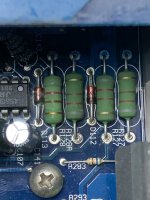
• there are two sets of power resistors/zener diodes for the 15v regulation, both sets measure identical.
Does heating or cooling the differential amp transistors make a difference?
•I tried this earlier to no avail.
• I’ll give this a try and report back in a bit.
This assumes that you are 100% sure that the signal is clean going into the diff amp.
Are the regulated voltages (±15v) as they should be?
• there are two sets of power resistors/zener diodes for the 15v regulation, both sets measure identical.
Does heating or cooling the differential amp transistors make a difference?
•I tried this earlier to no avail.
Attachments
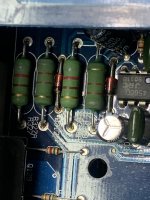
I swapped out the diff pair from the know working channel to one of the problematic channels, waveform remained unchanged, still not a clean sinewave above 10khz.
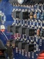
On another problematic channel I replaced all the to92 transistors with new, this also resulted in no change to the output waveform.
On another problematic channel I replaced all the to92 transistors with new, this also resulted in no change to the output waveform.
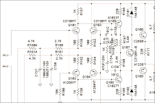
Have you tried increasing the current through the differential amplifier by slightly reducing the value of the resistors that feed them regulated voltage? The resistors would be R160A and R161A in the generic diagram below.
Are you 100% sure that this is a new problem. With music, this might be difficult to hear (especially considering that there isn't much at or above 10kHz) and to have it all of a sudden become a huge problem could mean that there is another problem in the vehicle.
Are you 100% sure that this is a new problem. With music, this might be difficult to hear (especially considering that there isn't much at or above 10kHz) and to have it all of a sudden become a huge problem could mean that there is another problem in the vehicle.
Attachments
I haven’t messed with altering the circuit. The amplifier appears to be original throughout, no repairs previously performed.
I have to double check this, but whilst comparing voltages to the good channel, none of the transistors had +/-15v on them, all measured rail (+/-28vdc) accordingly both good and discrepant channels.
When connected to speakers the audio is heavily distorted, when looking at the amplifier outputs with the scope all I could find were the variations in the output waveforms at 10khz and above.
Attachments

Yes,
They measure 0.4 ohms to RCA sheilds and center tap on transformer sec.
And 0.971kohm to primary/power ground.
They measure 0.4 ohms to RCA sheilds and center tap on transformer sec.
And 0.971kohm to primary/power ground.
Is the distortion the same (only above 10k) at all levels?
If you play a pure sine wave, at 100Hz, 1kHz, do they sound distorted even though looking perfect on the scope?
If you play a pure sine wave, at 100Hz, 1kHz, do they sound distorted even though looking perfect on the scope?
Is the signal still clean at the input to the differential amplifier when loaded?
The same, all loaded channels?
The same, all loaded channels?
- Home
- General Interest
- Car Audio
- Crossfire BMF 600.4 frequency response