Hi,
Is the primary winding start of the output transformer b+ or p? Is the secondary start at 0r or 8r? What is your advice?
Is the primary winding start of the output transformer b+ or p? Is the secondary start at 0r or 8r? What is your advice?
No. The B+ supply is a short to ground at AC and a transformer does not invert phase by convention. Although sometimes "dot" labeling is used on winding diagrams to avoid any confusion. So the B+ end of the primary winding should be aligned with the "common" of the secondary winding (or 0R in your diagram). Swap your output or input and you'll have the windings properly in phase.Is it correct in the picture?

Nope. Invert the secondary. Inverting the primary is calling for more potential troubles due to the higher contribution of the outer sections to capacitance.
P, where the anode is, has the highest voltage potential windings related to the secondary, this is where the highest capacitance is. So, for most output transformers, if logically constructed, have the anode layers at the bottom, where the lowest Mean Turn Length (MLT) is located. Lower MLT gives a lower surface area, so this results into lower capacitance.
On top of that, some transformers manufacturers, including me, asymmetrically distribute dielectric thicknesses, bringing thicker and/or lower epsilon dielectrics to the anode layers and thinner, higher epsilon dielectrics to the B+ layers. In that case, reversing primary polarity will further worsen the primary capacitance, compared to equal and symmetrical dielectric wound output transformers.
Reversing the secondary however should bring little trouble for most OPTs, as the secondaries are low impedance windings.
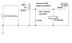
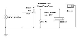
In simple wound OPTs such as the Hammond 125D there is a significant difference in capacitance
from each end of the primary to the core. Here are some measurements I took a few years ago.
The 0.92 M is a One Meg resistor in parallel with the 10M scope probe.
In measurements done much earlier, I think circa 1960 or before I measured ~200 pF
from one end of the primary to the core using a bridge method. That test on a Hammond 1618 OPT
of that time. Gotta find that file, Its still here somewhere I think.
Attachments
- Home
- Amplifiers
- Tubes / Valves
- SE Tube Amp OPT