
D
Deleted member 550749
D
Deleted member 550749
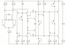
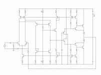
Bjt under the LED , also connected with CCS current section, with another led , this is not complete schematic and with ground it's works same normal pre driver and it's works also lower the distortion, output not drawed , it's jus draw or concept, if anyone wants to go with it, also compensation with 2 cap or single drawed , I m not an engeneer but I know the little bit and do things 🙏😊
Attachments
D
Deleted member 550749
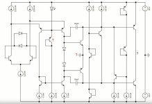
Removed ground and connected with the output, looks like it's a CFP configuration,
 I think it's better than that ground 🙏
D
Deleted member 550749
You have a weird approach of designing.I m not an engeneer but I know the little bit and do things.
In reality, the interaction is mainly with the load: what's connected to the output?
How can that be realized? That's the output stage.
How can this output stage be controlled? That's the stage in front of it (VAS, or immidiate).
How to control that stage and interact with the input? That's obvious.
What are the supply demands? Depends on the load and requested performance.
What topology is most suitable for the task involved?
How does the design behave in simulation, in open loop (the Bode plots), during powering up & down?
How does an amplifier perform in reallity? Distortion, sonic quality (subjective, but relevant though), thermal stability, reliability, durability.
Countless issues to address in advance of posting... graffiti?
D
Deleted member 550749
Yes, u can say it's weird approach, I think I need more study or knowledge and propper equipments, thanks
D
Deleted member 550749

- Status
- Not open for further replies.
- Home
- Design & Build
- Electronic Design
- Op amp schematic draw just for fun