I’m about to embark on building the Lampucera DAC, as described by Serbian YouTube star iiWi, You can see the video here:
He claims this is the best DAC he has ever had in his listening room.
The DAC is a precursor to the Lampizator line developed by Lucasz Fikus. Details, documentation, from iiWi here:
https://drive.google.com/drive/folders/1MvSMdEsZ8DPtGMXrzUgQ7ceyAVS86uxO?usp=sharing
Ebay starting kit from HKaudio1 (Lawrence, who has been very responsive):
https://www.ebay.com/itm/1863217614...zPANM_6Rl2&var=&widget_ver=artemis&media=COPY
I’m probably not going to use Lawrence’s included tube output stage, instead following iiWi’s version with the 6N6P [but maybe experiment with the eBay one first].
My first two question areas, for which I am seeking advice:
1. What do you recommend as a source for metal chassis that is easy to mod, and large enough for transformers and giant capacitors as iiWi had?
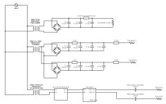
2. If you look at the schematic, it is based on 220V transformer on input. I have US 120V input. What transformer changes are needed?
If anybody has done this, and/or has advice to offer, I’d be most appreciative.
He claims this is the best DAC he has ever had in his listening room.
The DAC is a precursor to the Lampizator line developed by Lucasz Fikus. Details, documentation, from iiWi here:
https://drive.google.com/drive/folders/1MvSMdEsZ8DPtGMXrzUgQ7ceyAVS86uxO?usp=sharing
Ebay starting kit from HKaudio1 (Lawrence, who has been very responsive):
https://www.ebay.com/itm/1863217614...zPANM_6Rl2&var=&widget_ver=artemis&media=COPY
I’m probably not going to use Lawrence’s included tube output stage, instead following iiWi’s version with the 6N6P [but maybe experiment with the eBay one first].
My first two question areas, for which I am seeking advice:
1. What do you recommend as a source for metal chassis that is easy to mod, and large enough for transformers and giant capacitors as iiWi had?
2. If you look at the schematic, it is based on 220V transformer on input. I have US 120V input. What transformer changes are needed?
- A. Best to stick with toroidal transformers? Seems like a lot of audio guys prefer laminated. Can you recommend any source that is up to the standard here?
- B. I assume it’s easy to find a 120V to 6.3V transformer for tube heater. Any suggestions?
- C. It looks like the anode supplies start with 120V. Does that mean I don’t need any transformers for them?
If anybody has done this, and/or has advice to offer, I’d be most appreciative.
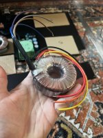
Attachments
Last edited:

A: shouldn't make much difference for power supplies.
B: I wish separate 6,3V transformers were easy to find (YMMV) but you can use a higher voltage one and adjust the series resistor accordingly.
C: You can skip the 120V transformer if you want to turn your DAC into a death trap.
B: I wish separate 6,3V transformers were easy to find (YMMV) but you can use a higher voltage one and adjust the series resistor accordingly.
C: You can skip the 120V transformer if you want to turn your DAC into a death trap.
Toroidal or R-Core would be the way to go here--lower EMI and lower profile. Buy "locally" if possible. I have used Antek many times in the US (they are not produced locally but ship locally 🤷♀️) but there's plenty of other options.
I looked at Hammond and Antek choices and they don't appear to have exactly what you need. Antek has one 50VA choice which includes 2x 6.3A heater secondaries.... But with only 1 120V secondary rated at .2A.
Based on the 80VA requirement, I think you need at least ~.3Amp per channel.
But I wonder if that's really necessary. Feels like a huge amount for a 6N6P.
If you think that the 120V notation suggests you can use the AC from the wall, I am a little worried about the upcoming build. That would be very dangerous since, in the event of a fault, your entire mains supply would be shorting into components/chassis.
You should get a transformer with 2x 0-120V secondaries, or two transformers with a single 0-120V secondary. Maybe check TME?
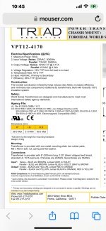
Any thoughts on this all-in-one solution?
Antek AN-61115. Seems to have everything jumbo size. My home voltage is closer to 120VAC than 115. Will that matter? Seems like this would be loafing compared to its capacity. From the schematic I need:
2 x 120V (80VA total)
1 x 6.3V (30VA)
1 x 12V (20VA)

Antek AN-61115. Seems to have everything jumbo size. My home voltage is closer to 120VAC than 115. Will that matter? Seems like this would be loafing compared to its capacity. From the schematic I need:
2 x 120V (80VA total)
1 x 6.3V (30VA)
1 x 12V (20VA)
Antek also recommended separate transformers, including the AU-12115 for the two 120V requirements. This one, while more modular, and better sized to the task, is an “AU” series, instead of an “AN” series, as above. The AN’s are targeted to low noise application such as “high end audio” whereas the AU series is targeted for industrial applications. I don’t know whether that’s really an issue or not.
Any thoughts?
I’m not clear on the advantages/disadvantages of using one big transformer with lots out outputs vs using separate transformers for each requirement.

Any thoughts?
I’m not clear on the advantages/disadvantages of using one big transformer with lots out outputs vs using separate transformers for each requirement.
I uploaded the circuit diagram to Claude, an AI similar to ChatGPT. I asked Claude where i should ground the circuit, as the ground is not shown on the diagram.
This is what I got back:
Looking at the diagram, you can connect the ground to the negative side of the bridge rectifier, which is typically the center tap of the high voltage secondary winding on the power transformer.
Specifically, you can ground the circuit at the junction between the two filter capacitor banks (470uF capacitors) following the bridge rectifier. This point is at 0V potential and serves as the ground reference for the B+ high voltage supply rails going to the tube anodes, as well as the separate heater supply.
Pretty impressive. Is it correct?
Last edited:
No.Is it correct?
Don't connect two bridge rectifiers to the same power power transformer winding.
There has to be a ground or circuit-common somewhere associated with each power transformer winding, otherwise no current can flow. No grounds or circuit commons at all are clearly shown in the diagram anyway.
Also I am relying on the schematic you posted, not anything written. If you want to know if a circuit is okay or not, best to post it fully in schematic form.
In addition, AC line ground must be connected to the metal chassis on the AC line side of the transformers.
Maybe trying reading this for starters: https://www.amazon.com/Designing-Power-Supplies-Amplifiers-Second/dp/0956154549
Last edited:
- Home
- Source & Line
- Digital Source
- Build Thread: Lampucera DAC (iiWi version) - help needed