Power 1000a1 PC-2666H
When I received this amp it was staying in protect. U21 pin7 was high even though pin 6 was well above pin 5 which was at 5 Vdc.
I replaced it and the amp comes out of protect with the delay as it should.
It does produce audio, but when a sine wave is driven into the amp, as the signal increases there is quite a bit of oscillation.
When music is driven into the amp it looks clean though.
I am using the schematic in the tutorial 'BD110001BB.sch-2' and this amp is similar, but it does not have the phase switch, or any switch for that matter, just low pass and gain pots.
My question is, I have dc offset of (-)76mV across the speaker terminal. (black on neg., red on pos.)
Should I try and improve this?
This is the first of the BD type amps I have worked on so I am not sure if this is acceptable.
A load across the speaker terminals does not change it.
I am also seeing it on pin 7 of U11 and it also appears as if the carrier is riding on this dc also.
One thing I notice is that the signal on the source of the audio switching transistors is about 1/10th the amplitude of the spikes in the images in the tutorial.
Vgs on the switching transistors are ~ 70 mVdc, black on gate, red on source. No Signal.
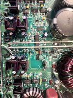
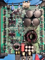
Attachments
Last edited:
That VGs isn't enough. How are you measuring it?
What is the DC voltage measured directly across the inputs (pins 2 and 3) of U17?
DC voltage on pin 1 of U4 with the black probe on pin 3 of U17?
DC voltage on pin 7 of U11?
What is the DC voltage measured directly across the inputs (pins 2 and 3) of U17?
DC voltage on pin 1 of U4 with the black probe on pin 3 of U17?
DC voltage on pin 7 of U11?
I edited my first post to say I found dc on pin 7 of U11. My apologies I first wrote pin 7 of U17.
Vgs measured black probe on source, red probe on gate. 9.445 Vac and (-) 63 mVdc. No signal input to amplifier.
U17
pin 2 (Red) to pin 3 (Black): (-)0.0001 Vdc
Pin 6: (-)0.0026 Vdc
U4:
Pin 1: 0.0112 Vdc with black probe on Pin 3 of U17
U11:
Pin 7: -0.0602 Vdc
Vgs measured black probe on source, red probe on gate. 9.445 Vac and (-) 63 mVdc. No signal input to amplifier.
U17
pin 2 (Red) to pin 3 (Black): (-)0.0001 Vdc
Pin 6: (-)0.0026 Vdc
U4:
Pin 1: 0.0112 Vdc with black probe on Pin 3 of U17
U11:
Pin 7: -0.0602 Vdc
I don't see any problems. The 76mv isn't awful and insignificant for a subwoofer amp.
If you simply want to try to get it down, you could try a different IC in U17. It believes that the offset is essentially nothing because its inputs are essentially nothing (0.000v).
What multimeter are you using that has 4 places to the right of the decimal and can read the AC voltage (seemingly accurate) across the G-S?
Email me if you want the latest version of the tutorial.