Hello,
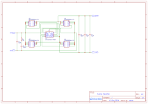
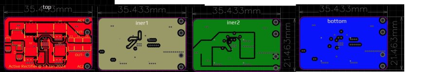
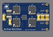
just to share an active rectifier, vertical mount, I designed for those who need to pair it with an clasic transformer based power supply, for those interested all the details is on pictures including gerber and bom file! I'm not tested it, but I have plan to build one for me, enjoy! : )
Features:
gerber file -> https://www.diyaudio.com/community/attachments/gerber_active-rectifier_pcb_2024-02-22-zip.1276544/
bom file -> (suplier www.lcsc.com) -> https://www.diyaudio.com/community/attachments/bom_active-rectifier_2024-02-22-zip.1276552/
just to share an active rectifier, vertical mount, I designed for those who need to pair it with an clasic transformer based power supply, for those interested all the details is on pictures including gerber and bom file! I'm not tested it, but I have plan to build one for me, enjoy! : )
Features:
- Maximizes Power Efficiency
- Eliminates Thermal Design Problems
- DC up to 600Hz
- 9V to 72V Operating Voltage Range
- IQ = 1.5mA (Typical)
- Maximizes Available Voltage
gerber file -> https://www.diyaudio.com/community/attachments/gerber_active-rectifier_pcb_2024-02-22-zip.1276544/
bom file -> (suplier www.lcsc.com) -> https://www.diyaudio.com/community/attachments/bom_active-rectifier_2024-02-22-zip.1276552/
Attachments

Last edited:
Thanks for sharing this LT4320 active rectifier.
For a better DIY soldering success rate, please consider changing the LT4320 DFN package to MSOP12. DFN’s are nearly impossible to solder if you don’t have a lot of smd soldering experience.
For a better DIY soldering success rate, please consider changing the LT4320 DFN package to MSOP12. DFN’s are nearly impossible to solder if you don’t have a lot of smd soldering experience.
Hi, this is all smd! If I add trought hole I must redesign whole pcb which is not an good idea. I realy not like trought hole components. : )
I understand this is an all SMT design, so is MSOP12.
https://mou.sr/3T7kdpj
I am pretty good with smd soldering and this was just suggestion for easier soldering for non-experienced builders because the legs are exposed. If you keep the DNF package, slightly extend the solder pads so a fine tip iron can touch up soldering if needed.
https://mou.sr/3T7kdpj
I am pretty good with smd soldering and this was just suggestion for easier soldering for non-experienced builders because the legs are exposed. If you keep the DNF package, slightly extend the solder pads so a fine tip iron can touch up soldering if needed.

Yes but it also reguire thermal pad to be soldered by hot air gun and it is than no diference than soldering one with exposed pad, right? In my opinion its easier to solder DFN than MSOP12. To be honest I don't have free time for modification on pcb sorry! Idea was to make it as small as possible.
Thanks for sharing the PnP file😁
I’ve been curious why you chose the triple capacitor combo between outP and outN instead of the data sheet spec’ed 1uF ceramic?
Have you experimented with this combo?
Cheers,
Vunce
I’ve been curious why you chose the triple capacitor combo between outP and outN instead of the data sheet spec’ed 1uF ceramic?
Have you experimented with this combo?
Cheers,
Vunce

- Home
- Amplifiers
- Power Supplies
- Active Rectifier