Within this post,
https://www.diyaudio.com/community/threads/hometaxial-2n3055-mj2955.350298/#post-6099879
post #4 claims that emitter resistors can be avoid when replacing the 2N3055/MJ2955 pair in NAD 3020 type amps if at least one is old style hometaxial.
Would selecting any one from each of the two following sets meet this condition, ie. 1. are they all genuine, and 2. are the 2N3055's hometaxial (since apparently there are no hometaxial Motorola MJ2955's)?
Thanks,
Attachments

Last edited:
I did not see anything about emitter resistors. Eliminating these: Just wait for disaster.
In post #5 it mentions base resistors though. That would depend on the design, which is not given. E
In post #5 it mentions base resistors though. That would depend on the design, which is not given. E
I'm not sure if I understand this correctly then. On my schematic for the 7020e, there are no emitter resistors. I thought that its design is based on hometaxial 3055/2955 and thus excluded the emitter resistors. If I replace with epitaxial 3055/2955 then emitter resistors would be necessary. Post #4 from the link indicated above, as I read it, claims that if one from the pair is hometaxial, then they will likely be thermally stable. Does this not mean I can forgo the emitter resistors (leave the circuit as is)?
Attachments
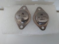
The one on the right is probably the only hometaxial in the bunch. 1967 date code, that’s all they made back then. Motorola never made one, RCA made both for a while. But no clue when that RCA was made so you can’t be sure. Later ones were given type # 2N3055H.
Base resistors were a band aid that worked with newer types. Emitter or base resistors have similar thermal feedback. They also have similar electrical feedback. Transistor types that have a high Rbb internally may as well just have emitter resistors - the “degradation“ to the sound is the same. All you really do is get to say “Look, my design gets away with no (crossover-distortion-generating) emitter resistors!” But it isn’t any better off.
Base resistors were a band aid that worked with newer types. Emitter or base resistors have similar thermal feedback. They also have similar electrical feedback. Transistor types that have a high Rbb internally may as well just have emitter resistors - the “degradation“ to the sound is the same. All you really do is get to say “Look, my design gets away with no (crossover-distortion-generating) emitter resistors!” But it isn’t any better off.

Thank you for the clarification.
In sum then, going with the hometaxial+epitaxial pair, it is likely that I'll avoid modifying the (questionable) design of omitting emitter resistors but I may have to (either emitters or base). Good practice would have had them to begin with to avoid feedback problems, but the accountants got in the way.
Would even better practice add these resistors for the other still working channel with the original hometaxial pair?
Check out Nad302, 312, 304 and 314, who all used more modern Sanken output transistors and no emitter resistors!!
Schematics are at hifiengine.
Schematics are at hifiengine.
Thanks for the tip.
I had a quick look at the 302 schematic. 2N3055 -> 2SC3519, MJ2955 -> 2SA1386. Need to check more closely but the circuits looks identical and the voltages are close. There's examples on the internet where TO-3P components are adapted to fit into a TO-3 slot.
I had a quick look at the 302 schematic. 2N3055 -> 2SC3519, MJ2955 -> 2SA1386. Need to check more closely but the circuits looks identical and the voltages are close. There's examples on the internet where TO-3P components are adapted to fit into a TO-3 slot.
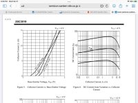
Look at the Vbe/Ic curves. They go linear at high currents. What does that tell you about the construction? (Also the R has a positive temperature coefficient).
The LAPT type can often be used without external emitter resistors. At relatively low Vce - dont try this on +/-80V rails where you need to parallel a bunch of them.
Even the original 2N3055 is a relatively big device for the application. I’ve seen many many many receivers from the 80’s and 90’s using 2SD525/B595 on the same +/-30 volt rails. They wouldn’t do 4 ohms, of course - and not at all without emitter resistors.
Attachments
I appreciated the detailed response. This is above my level of comprehension, I can only surmise that you are highlighting the dangers of blind transistor substitutions. I'll take a stab at disseminating what you're saying.
I'm guessing that you are pointing to some aspect of thermal stability here. The linearity at higher currents is indicating that the current increase (delta-I) for a given voltage change (delta-V) at relatively lower Vbe/Ic level has increased at higher levels, ie. at higher levels of Vbe/Ic , the given voltage change (delta-V) is associated with a larger delta-I. I assume meansrelatively more heat and then more thermal instability risk (? because there is no asymptotic/convergence behavior).
I know nothing about what this implies about the construction.
For someone at my level of knowledge, it's probably best to stick with the 3055/2955 combo and add resistors to fix the amplifier. I'll come back when I encounter more hurdles.
Thanks again.
The Sanken LAPTs have a small parasitic resistance due to internal ballasting of the multiple cells. Better thermal stability than types which do not have it. The old hometaxial 3055 had excess bulk base resistance, but that was just because it was a POS. When modern types “improved” this, they became less thermally stable. When making good rugged fast transistors, the best way to do it is with multiple parallel cells on one die - or at the very least, multiple emitter fingers. This requires base and/or emitter “resistors” internally. They are just an order of magnitude less R than you normally see in an amplifier. But make no mistake- they are still there. RCA experimented with it early on, and the result was things like the 2N5240. Sanken does it with their epitaxial planar process, Toshiba does it with their triple diffused. Both are the kings of their respective hills.
The internal R values (between .01 and .05 ohm) are not high enough to run without emitter resistors in circuit at elevated Vce or when paralleling multiple units which may not see absolutely identical thermal resistance. But at sufficiently low Vce you can get away with it. Personslly, I think +/-30 is a bit high to get away with it, but at 15 or 20 you absolutely can.
If you are using 2N3055’s (or MJ15003’s) just add 0.1 ohm emitter resistors, or 2.2 to 4.7 ohm base resistors and call it good. I’d still do that with LAPTs, and never worry about it running away.
Last edited:
Sounds like a plan! Thanks.
In your opinion, are Sanken LAPTs (say 2SC3519) sonically superior to 2N3055s?
In your opinion, are Sanken LAPTs (say 2SC3519) sonically superior to 2N3055s?
They are better transistors in almost every way. Does that mean the amp will be any better? Often not noticeably.
- Home
- Amplifiers
- Solid State
- NAD7020e: Avoiding Emitter Resistors 3055/2955