Philips n2400 Casette Deck
I only use this part of the circuit, I need to make a preamp can you help me?
Since the circuit is a cassette player circuit, I disabled its own preamp section (due to hum noise).As a result, output watt is reduced by approximately 60%.
Can you help me by making a circuit diagram?

I sometimes use this circuit, which I removed from its own circuit, as a tone control.

I will be grateful if you could help me.
I only use this part of the circuit, I need to make a preamp can you help me?
Since the circuit is a cassette player circuit, I disabled its own preamp section (due to hum noise).As a result, output watt is reduced by approximately 60%.
Can you help me by making a circuit diagram?
I sometimes use this circuit, which I removed from its own circuit, as a tone control.
I will be grateful if you could help me.
Unfortunately this tone control network needs to be driven by a lowish impedance source. What precedes it in the complete schematics?
Best regards!
Best regards!
İptal ettiğim bölüm geliyor

Tone control is not very important, I use it sometimes, I need a preamp circuit like the part I canceled, I couldn't do it.
Tone control is not very important, I use it sometimes, I need a preamp circuit like the part I canceled, I couldn't do it.
Last edited:
İptal ettiğim bölüm geliyor
 English please.
Translation...
The part I cancelled is coming.

Kusura bakmayın, çevirerek yazıyorum. Çok iyi ingilizce bilmiyorum.
Translation: Sorry, I'm translating it. I do not know English very well.
It is not possible to solve this problem in Turkey. There are people here with serious experience, I think they can help 😊
Translation: Sorry, I'm translating it. I do not know English very well.It is not possible to solve this problem in Turkey. There are people here with serious experience, I think they can help 😊
Last edited by a moderator:
https://translate.google.com
This will increase the gain of the amp ~60%.
It is not perfect, but can help a little.
Change R604 from 18k into 39k, but also change C780 from 390pF into180pF.output watt is reduced by approximately 60%
This will increase the gain of the amp ~60%.
It is not perfect, but can help a little.
Even a 30% increase would work for mehttps://translate.google.com
Change R604 from 18k into 39k, but also change C780 from 390pF into180pF.
This will increase the gain of the amp ~60%.
It is not perfect, but can help a little.
This variability wouldn't stress the transistors, would it?
Will I have any problems with sound output?
My aim is just to compensate for the decrease in sound caused by the preamps I disabled.
Best regards !
Last edited:
Add the stage around T433 and see.
Best regards!
I removed these preamps from the circuit one by one and while removing them, I tried the audio input as a, b, c respectively. When I log in from section A, the sound is normal and as it should be. When I disable section A and enter from B, the sound sounds very thin and meaningless. When I disable part A and B and enter only from C, the sound is very muffled. So I took it out completely and threw it in the trash 😔
I'm currently only using the amplifier section and would like to solve this lack of sound with a new opamp or some other means if necessary.
Best regards !
Did you regard that the voltage divider R600/R604 defines the center voltage, aka voltage at the output transistors' emitter resistors, or positive end of C782?https://translate.google.com
Change R604 from 18k into 39k, but also change C780 from 390pF into180pF.
This will increase the gain of the amp ~60%.
It is not perfect, but can help a little.
Best regards!
Yes, I see three points A, B, and C in the schematics. But they relate to three different points in the power supply filtering?!? So I'm very astonished that you heard something at all.I removed these preamps from the circuit one by one and while removing them, I tried the audio input as a, b, c respectively. When I log in from section A, the sound is normal and as it should be. When I disable section A and enter from B, the sound sounds very thin and meaningless. When I disable part A and B and enter only from C, the sound is very muffled.
Best regards!
No, I just tried inputting audio by disabling preamps a, b, c one by one and wrote down the result. The reason I wrote a,b,c is to indicate the preamp sections.
Can I solve it this way? Do I need to make any other changes? Or will this damage the amplifier?R600/R604 voltaj bölücünün merkez voltajı, yani çıkış transistörlerinin verici dirençlerindeki voltajı veya C782'nin pozitif ucunu tanımladığını dikkate aldınız mı?
Saygılarımla!
Leave this voltage divider, it is important also for the DC balance adjustment, as I said.
When you checked the amplifier section for section, did you disconnect the previous section in every step? I don't see any reason why the amp should sound muffled when you inject signal into the positive lead of C753. You need to short R581 and leave out both R637 and C809, though. If the amp works this way, C753 needs to be swapped, i. e. negative end to the input terminal with a 100k resistor to common ground. And C782 needs to be increased to 2200 µF at least for better LF response.
Best regards!
Currently there is only the amplifier part. I threw away the other parts. I will replace C782.
If you can help draw another preamplifier I can do that. Or can't I fix the lack of sound by just changing the amp part?

If you can help draw another preamplifier I can do that. Or can't I fix the lack of sound by just changing the amp part?
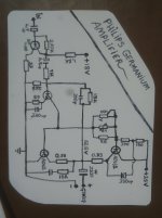
Did you remove the IEC preamplifier.?.
Are you connecting the magnetic head directly to the circuit in post 16.?.
Are you connecting the magnetic head directly to the circuit in post 16.?.
No, my fault. That would freeze the mid setpoint to the pos rail. Thanks for notifying.Did you regard that the voltage divider R600/R604 defines the center voltage, aka voltage at the output transistors' emitter resistors, or positive end of C782?
You need a capacitor in series with R598Currently there is only the amplifier part. I threw away the other parts. I will replace C782.
If you can help draw another preamplifier I can do that. Or can't I fix the lack of sound by just changing the amp part?
View attachment 1270322
.47 to 10uF , positive towards transistor base.
Leave amp as is, messing with its gain will change bias the wrong way.
Add a preamp before it as needed..
- Home
- Amplifiers
- Solid State
- Philips Germanium Amplifier, Problem