Hey guys. This is a long shot - does anyone have a schematic for this TM1000X5ad amplifier? This is a marine amp that is still being produced so Rockford won’t give out any diagrams.
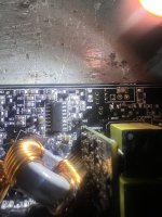
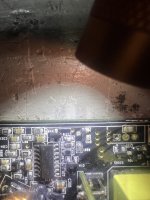
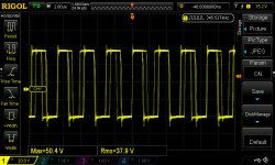
It came in with Q1 and Q10 (IRFB4115) short. I removed the whole side and I moved two over from the other side to fit one in each bank. When the amp powers up, the low side has a normal looking pattern but it appears there’s about 28V leaking into it. Also, when you flip the amp over, I have two fets (IRFR4510’s) hot and their associated output inductor is getting hot as well. These fets do not appear to be marked with any associated Q’s so it’s hard to describe it. It would be the upper left two when the amp is flipped over.
I can’t tell if this is a two part problem or if it’s all related. On the top side D2012 (BAV99 or A7) has low side oscillation on pins 1 and 3 but 28V on pin 2. On the other working side it has only 8V or so.
I’m starting to get stumped on this one. I’d like to get the Q10 and Q1’s gates cleaned up - I can’t find the drive circuit for it, it’s nearly impossible to trace it with everything black and covered in marine grade coating. And I’d like to find out why the two fets on the bottom are getting hot.
Attachments
Last edited:
What driver ICs is it using for outputs?
Are they buffered or do they drive the output FETs directly?
Are they buffered or do they drive the output FETs directly?
Hey Perry,
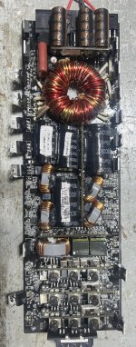
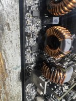
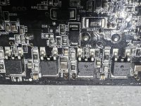
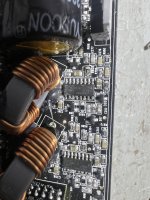
The drivers for the eight IRFR4510’s on the bottom are IRS2092's. The low side is connected via a 10 ohm resistor directly to the gates, and the high side is connected via diodes and such.
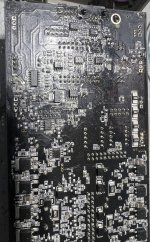
The two IRF4510's getting hot on the bottom are on the same side as the gate pads with the bunged up drive pattern/leaky voltage on the IRFB4115's. I can't seem to find the drivers for the IRFB4115's at all. They do appear to be buffered yes with I'm assuming that there are 8 pin drive IC's that would connect to these transformers that Rockford loves to use. I just can't figure out where they would be by tracing them.
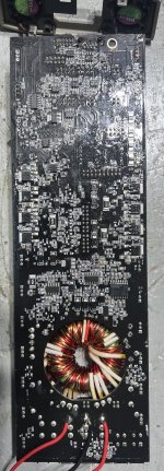
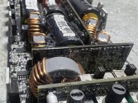
I'll show you some more pictures. Maybe you've seen this type of amp before. This is a 5 channel amp, with the sub channel that's supposed to be able to handle 1ohm. The original complaint that was the music sounded distorted and then it keeps shutting off. I can get it to turn on now after removing the dead IRFB4115's but as soon as the bottom fets get too hot the amp keeps restarting.
The drivers for the eight IRFR4510’s on the bottom are IRS2092's. The low side is connected via a 10 ohm resistor directly to the gates, and the high side is connected via diodes and such.
The two IRF4510's getting hot on the bottom are on the same side as the gate pads with the bunged up drive pattern/leaky voltage on the IRFB4115's. I can't seem to find the drivers for the IRFB4115's at all. They do appear to be buffered yes with I'm assuming that there are 8 pin drive IC's that would connect to these transformers that Rockford loves to use. I just can't figure out where they would be by tracing them.
I'll show you some more pictures. Maybe you've seen this type of amp before. This is a 5 channel amp, with the sub channel that's supposed to be able to handle 1ohm. The original complaint that was the music sounded distorted and then it keeps shutting off. I can get it to turn on now after removing the dead IRFB4115's but as soon as the bottom fets get too hot the amp keeps restarting.
Attachments
-
 IMG_0809.JPEG457.2 KB · Views: 76
 -
 IMG_0810.JPEG455.5 KB · Views: 63
 -
 IMG_0811.JPEG539.2 KB · Views: 69
 -
 IMG_0812.JPEG603.4 KB · Views: 70
 -
 IMG_0813.JPEG501.5 KB · Views: 64
 -
 IMG_0814.JPEG636.5 KB · Views: 69
 -
 IMG_0815.JPEG546.5 KB · Views: 72
 -
 IMG_0817.JPEG527.8 KB · Views: 66
 -
 IMG_0818.JPEG542.8 KB · Views: 64
The 2092 channel hasn’t failed by the looks. But the associated fets are getting hot.
The BD channel is the one that has failed. I just can’t figure out where the drives are. I’m thinking it maybe piggy backing off the 2092’s somehow. shrug
I remember the old BD amps used an 8 pin driver and a transformer for the gates. I know where the sub preamp is in that God awful pile of cards but I don’t have any pinouts for it.
What's the part number on the BD driver card?
If you pull the BD outputs, do the other 4 channels work?
Are all of the FETs under the board for the 2092 channels?
Do all of them get hot?
If you pull the BD outputs, do the other 4 channels work?
Are all of the FETs under the board for the 2092 channels?
Do all of them get hot?
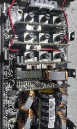
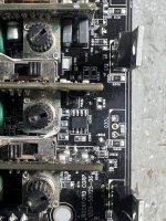
See the attached photo. I’m assuming this is the BD driver card but I’m not 100% sure. Maybe the drivers I’m looking for are on that card?
The card right along side of it is the sub preamp card.
The 2092 fets (all 8 of them) are under the board. Only two of them get hot.
I’ll have to remove the 4115’s tomorrow and I’ll report back
The card right along side of it is the sub preamp card.
The 2092 fets (all 8 of them) are under the board. Only two of them get hot.
I’ll have to remove the 4115’s tomorrow and I’ll report back
Attachments
If those FETs (under the board have their gates connected to the output terminals of the 2092s, remove the gate resistors for the ones getting hot and see if there is any leakage (on ohms) between the gate terminal and the other 2 terminals. Do this for both FETs that are heating up.
Do you know how to check the output drivers on this type of driver IC? If not, I can probably get you through it.
Do you know how to check the output drivers on this type of driver IC? If not, I can probably get you through it.
I removed the gate resistors for the fets getting hot under the board - there doesn't appear to be any leakage from terminal to terminal. When put on diode check, the fet looks normal. I'm thinking of removing the fets when the amp finally loses its voltage after testing.
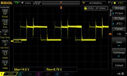
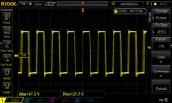
The driver IC doesn't oscillate with the gates not connected to the fets. So before I removed the gates, I took some readings. The only weird readings I get, are on pin 14 of the 2092s of the hot fets.
This appears to be a two part problem. The first problem, is that I have two fets under the board which drive the speakers are getting hot causing the amp to shut down. I'm assuming its because of the pin 14 output pattern which looks not so good. I'm going to try to switch places with a known good 2092 to see if that temporarily resolves the problem.
The second problem is on the sub output channel. The sub channel came in with blown fets on one side. When replacing the fets on both sides with known good working ones, the driver IC's for that channel (which I'm not sure of where they are yet) appear to be messed up. Now what are the chances this amp has driver IC problems on the speaker channel and the sub channel. Am I missing something here? Also, if I removed the BD Card from the amp, will I actually find a driver IC on it that could be wacky? It looks like it could be quite difficult to get out.
One more question. Why is this amp so difficult to desolder? I'm using a 70W iron and I won't lie it's challenging to get the solder out from the pads. It's almost like the pad hole is small and the solder won't melt all the way through as this board is somewhat thick. I'm worried that leaving my iron on too long will delaminate the pad and make things much worse. Rockford amps trick me quite a bit I won't lie!
Attachments
-
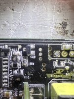
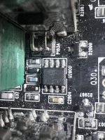
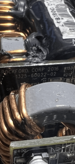
 Bad gate pad to 4115's, fets removed.jpg69.1 KB · Views: 55
 -
 Good gate pad to 4115's, fets removed.jpg66.4 KB · Views: 50
 -
 Bad gate pads when fets installed - low side.jpg67.9 KB · Views: 54
 -
 Pin 14 of IRS2092 - fets that dont get hot.jpg76.2 KB · Views: 47
 -
 Pin 14 of IRS2092 - fets that got hot.jpg81.8 KB · Views: 53
Do you have any ChipQuik? If not, that would help prevent damaging the board.
A combination of tight through-holes, multi-layer boards and heavy copper can make desoldering a problem. You definitely don't want to damage the board because you may lose connection to an inner layer.
I have never seen that driver board so I can't answer the driver questions. I may be able to determine what's on it if you get it out.
Are you using your scope in differential mode?
Battery powered scope (not likely with 4 channels)?
Where is the scope ground?
Hey Perry,
I’m using a Rigol DS1054Z with a 50MHz probe. My ground is connected to the amps main ground.
And yes, I’m likely going to have to remove the BD driver card to see what’s the scoop. I have a few wires from an old arduino kit so I can work with the board off of the main board - if need be.
I’m using a Rigol DS1054Z with a 50MHz probe. My ground is connected to the amps main ground.
And yes, I’m likely going to have to remove the BD driver card to see what’s the scoop. I have a few wires from an old arduino kit so I can work with the board off of the main board - if need be.
OK. Get the CQ (and the flux that goes with it) so you don't damage the board. Read #20 on the TT5 page of the tutorial.
Attached is the schematic for this amp.
Q22 is getting hot. When I try to diagnose it, I am confused. The input pin (pin 3) to the LM317 is at ground. The other two pins are at -22V. I’m not sure if this is correct or not.
I got the BD card out but for now am trying to see why this regulator keeps getting hot hot hot. I’d like to have the amp powered up to test it, but it seems impossible until I solve this problem first.
Attachments
Well the output is -22.5V or so. If I clamp the board back to the sink I won’t be able to work on it.
I haven’t seen a voltage regulator configured that way before. I’m just wondering if that’s the correct voltage coming off this thing with the input pin connected to ground.
Also, I’m going to investigate to see if anything is pulling that regulator hot, but no other IC’s on the board are getting that hot - just the regulator. I’ve replaced it and it’s doing the same thing. I didn’t have an LM317HV in stock so I slapped the LM317T in its place for testing.
According to the diagram, the output voltage should be roughly 12.5v. There is a calculator on the ATS page under item #25 if you have the tutorial. If not, the datasheet has the formula to calculate output voltage.
You have a couple of options for cooling. Extend the wires and use the original heatsink or clamp the regulator to something that will soak heat (any relatively thick piece of aluminum). See attached.
You have a couple of options for cooling. Extend the wires and use the original heatsink or clamp the regulator to something that will soak heat (any relatively thick piece of aluminum). See attached.
Attachments

- Home
- General Interest
- Car Audio
- Rockford TM1000X5ad Schematic