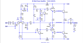

You should measure the current in R12.
And Bias Adjust for ~60mA.
That is like 20mV across R12.
And Bias Adjust for ~60mA.
That is like 20mV across R12.
R14 and R16 ahould be the same = 47k
Adjust R15 to this for the total Gain. For example make R15 = 2k2
Adjust R15 to this for the total Gain. For example make R15 = 2k2
Would replacing C1 C8 at the input with a single film cap help with sound and measurements too ?
Sorry, but it’s better when R14 and R16 are the same and = 10k, so the stability of the operating point at the amplifier output will be 4.7 times higher.R14 and R16 ahould be the same = 47k
Yes, it will help and it will be of higher quality.Would replacing C1 C8 at the input with a single film cap help with sound and measurements too ?
That is probably better.Sorry, but it’s better when R14 and R16 are the same and = 10k, so the stability of the operating point at the amplifier output will be 4.7 times higher.
In this case when R14 and R16 are 10k, so make R15 = 470 ohm or even 390 ohm.
It will be better not to change these values and leave 680 ohms. The fact is that with a supply voltage of +/-35 volts, it will not be possible to obtain a sine wave without limitation with more than an amplitude voltage of +/-27 volts due to the single-ended driver transistor. With an input voltage from a modern source (for example, a DAC) up to 2 volts amplitude, we get Ku = 27/2 = 13.5 and we get 10k/13.5 = 740 ohms, 680 ohms is still closer to the calculated version.In this case when R14 and R16 are 10k, so make R15 = 470 ohm or even 390 ohm
Dear lineup Sir as you said i changed the values. The RMS increases and also T.H.D is little bit high now.


Yes i think replacing film cap is a good idea i would try this.Would replacing C1 C8 at the input with a single film cap help with sound and measurements too ?
Of course THD is going to increase if the closed loop gain increases.
3 choices. Live with the slight increase in distortion, finagle a bit more loop gain out of the amp (a current mirror on the diff pair would do this), or add another stage of gain in front of everything (I think it’s called a “preamp”).
3 choices. Live with the slight increase in distortion, finagle a bit more loop gain out of the amp (a current mirror on the diff pair would do this), or add another stage of gain in front of everything (I think it’s called a “preamp”).
This thing isn’t actually that far removed from the (in)famous “DX amplifier”. Resistor in the LTP pair, bootstrapped NPN, +/-35 volts. It just used complementary outputs. This does add trimming of the LTP current to effectively force balance (if the input pair is matched, zeroing the offset this way should give equal current). But it does move the dominant pole around with it. Probably not enough to really matter.
Yes but if i remove 15v zener and only use 6.8k resistor with 47k resistor in series the T.H.D reduces to 0.006 only.This thing isn’t actually that far removed from the (in)famous “DX amplifier”. Resistor in the LTP pair, bootstrapped NPN, +/-35 volts. It just used complementary outputs. This does add trimming of the LTP current to effectively force balance (if the input pair is matched, zeroing the offset this way should give equal current). But it does move the dominant pole around with it. Probably not enough to really matter.
Should i remove 15v Zener to reduce T.H.D to 0.006 only?
But bias will be unstable.
Last edited:
There will be some current level in Q3 that forces exactly the right vbe on Q7 such that the output naturally (without DC feedback) goes to zero. You want that same current in Q3 and Q4. However that is achieved is the optimum for DC offset and for distortion cancellation. The input bias currents (base current of Q3 and Q4) also upset this a little. That’s why you want high hFE and the Q3 bias resistor and Q4 bias resistors to be the same, so their contributions to this mess are small and tend to cancel.
The circuit will still work if Iq in Q3 and Q4 are out of balance. DC offset may even still be relatively small. But the difference in distortion when you do get it balanced can be striking. The usefulness of negative feedback depends on the accuracy of the differencing between the two inputs. Where the differencing does not occur accurately, the G/(1-GH) equation breaks down you dont get the amount of distortion reduction that feedback theory tells you you’re supposed to get. A singleton input stage actually does better than a badly matched diff pair.
If you have trouble getting differential balance and low offset at the same time, the value of R20 is simply wrong. Its the knob you turn to correct that situation.
- Home
- Amplifiers
- Solid State
- Class AB 82 watt amplifier.