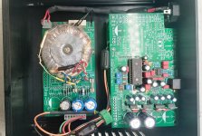
What would be the best way to hook up a left and right side pcb for a dac. Some diy designs on this forum have this set-up, but also the Andrea designs on The Well audio, and even Metrum and Rockna and more. And i do to 😉 The dac grounds and digital grounds on each pcb's are hooked up regarding datasheats: grounds connecteed below the chip.
Each power supply has his own winding.
example:

Let's hook up te separate PSU's. All good now Al grounds are still separated:

Now, connect the digital reciever. Now the grounds connect through the spdif signal wires. The digital reciever becomes the star ground point. That don't looks the best point, or not?

If you would connect a ground link between left and right dac boards then factual you create one pcd regading grounds with a better more low impedance ground?:

And you can even connect chassis:

What do you guys think? Am i overthinking this ideal ground point and stick to image 3 or hook-up like one of the last images?
Each power supply has his own winding.
example:
Let's hook up te separate PSU's. All good now Al grounds are still separated:
Now, connect the digital reciever. Now the grounds connect through the spdif signal wires. The digital reciever becomes the star ground point. That don't looks the best point, or not?
If you would connect a ground link between left and right dac boards then factual you create one pcd regading grounds with a better more low impedance ground?:
And you can even connect chassis:
What do you guys think? Am i overthinking this ideal ground point and stick to image 3 or hook-up like one of the last images?
Last edited:
Not sure what you're trying to get at. TheWellAudio dac boards I am familiar with are only grounded by the u.fl connector for MCLK or BCLK (depending), and by the analog output connectors. The other digital signals are all galvanically isolated on the dac boards, then reclocked locally.
But where is the "star ground" point. And where is the chassis ground connection. Or al floating?

Chassis ground is connected to AC line ground. Circuit ground is connected to AC line ground through a hum-breaker circuit similar to the image below:And where is the chassis ground connection.
Obvious, but this situation seems a bit more complex with 2 dual mono pcb's. Actual there are 3 pcb's if you also count the digital reciever. And this reciever now connect's these two pcb's as one thrue the i2s signal grounds.
And where on these pcb's would you place these chassis to signal: the analog partor the digital part?
And where on these pcb's would you place these chassis to signal: the analog partor the digital part?
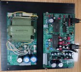
Regarding your image below:

Already I would say this is not the best way to do it. Each PSU should have two wires, not three. It means it takes two PSUs and two transformer windings to make +15v and -15v. Only connect the grounds together at the load PCB. Otherwise the shared ground wire causes crosstalk between the + and - power rails.
Regarding the digital receiver, it should be clocked from an external clock board. The USB board should be galvanically isolated from the dac boards. The I2S signals should be reclocked by the clock on the clean side of the isolators. A buffered copy of the clean clock is sent to the USB board through another isolator. Actually, this was all discussed in another dac thread.
EDIT: Some more info at: https://www.diyaudio.com/community/...t-register-firdac.379406/page-95#post-7460443
https://www.diyaudio.com/community/threads/return-to-zero-shift-register-firdac.379406/post-7461516
Last edited:
Thanks for your time Mark. Of course the dual psu's has 4 wires. The analog psu's are superregs. Your sugestions are superb, but also for now next (end) level.
Again, there are a lot of these set-ups in diy. Also commercial. Maybe the Metrum Pavane? How would you connect to chassis/earth?

Again, there are a lot of these set-ups in diy. Also commercial. Maybe the Metrum Pavane? How would you connect to chassis/earth?
Place chassis ground point near DAC chips analog ground pin.
Do not connect AC power PE contact to chassi.
Separate Signal ground trace and power ground trace.
Do not connect AC power PE contact to chassi.
Separate Signal ground trace and power ground trace.
If you're not using isolators, then there are a lot of little ground loops. In that case try to keep the loop areas as small as possible.How would you connect to chassis/earth?
Also if using I2SoverUSB, it tends to sound better if you use two isolated +5v supplies, rather than only one. Another thing about USB boards and or RPi: They tend to produce radiated and conducted EMI/RFI. Turning the USB board so that its ground plane side is pointing towards the dac boards may help reduce radiated noise coupling.
For safety reasons the circuit grounds with exposed parts, need to be connected to AC line ground with a hum-breaker circuit to make it safe and legal (and the chassis directly connected to AC line ground). However, you can use more than one hum-breaker circuit so that you don't create more ground loops than absolutely necessary. Exposed parts would include the output signal connectors and the USB input connector (if I2SoverUSB dirty side is powered by an an internal isolated +5v supply).
Last edited:
- Home
- Source & Line
- Digital Source
- Wiring dual mono DAC PCB boards