Hi, I have a pair of Sun Audio SV-300B mk2 amps which I guess are around 25 years old now.
They sound clear and detailed, but have a slighty forced edginess to the sound at times which I would like to improve on.
Most of the caps fitted are the original electrolytics and I'm interested to see if I can get an improvement in the sound by changing them all out for MKP film caps, so no electrolytics anywhere.
The general advice has always seemed to be "sure, that would be nice, but they will be huge and expensive" but it seems like that is not necessarily the case any more. Plus, in a simple amp design with mostly point to point wiring, there is some room to be creative with placement.
So I have got myself a load of Kemet C4AQ caps as they come in the specs I want at reasonable sizes/prices and they seem to be well regarded here.
I am now planning out how best to approach this.
I don't want to entirely bastardise these lovely amps, but it seems like I can probably do this in such a way as they look identical externally and if it's not a success, this change can always be reversed if I want.
I'm interested in any general advice on the plan, whether there's any considerations I may have missed, and any practical tips for working with these type of caps, like how others have mounted them. I may make some hold-down straps, or I'm wondering whether sticky pads or glue onto the flat chassis plus the soldered connection could be mechanically sufficient for most of them. I'd like to understand whether all 4 legs should be connected or can I snip/bend 2 of them out the way. That kind of thing.
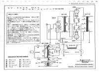
here's the schematic

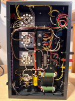
here's the existing layout internally

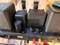
47uf+47uf cap from the CLC and the 2 x 100uf 300B cathode resistors poke out the chassis at the top, but they take up little room internally so can probably stay in place (disconnected)

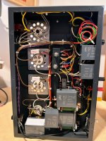
Here's a very rough test-fit of how the C4AQ caps could be placed (bottom left ones will fit further in with the electrolytics removed). It'll be tight in places, but it looks totally practical to get them where I want.

I feel I should assess the 47uf + 47uf in the B+ CLC whilst I do this as the Power Transformer gets quite hot in use and I wonder if that's cos 47uf is a bit large for a 5U4G input cap. So maybe that will end up being 40uf + 75uf instead. I have some different capacity options coming and plan to scope the various ripples.
The voltage ratings for the cathode bypass caps are excessive, but if they physically fit (which they do) is there any negative to that?
What do you think?
Any input gratefully received 🙂
They sound clear and detailed, but have a slighty forced edginess to the sound at times which I would like to improve on.
Most of the caps fitted are the original electrolytics and I'm interested to see if I can get an improvement in the sound by changing them all out for MKP film caps, so no electrolytics anywhere.
The general advice has always seemed to be "sure, that would be nice, but they will be huge and expensive" but it seems like that is not necessarily the case any more. Plus, in a simple amp design with mostly point to point wiring, there is some room to be creative with placement.
So I have got myself a load of Kemet C4AQ caps as they come in the specs I want at reasonable sizes/prices and they seem to be well regarded here.
I am now planning out how best to approach this.
I don't want to entirely bastardise these lovely amps, but it seems like I can probably do this in such a way as they look identical externally and if it's not a success, this change can always be reversed if I want.
I'm interested in any general advice on the plan, whether there's any considerations I may have missed, and any practical tips for working with these type of caps, like how others have mounted them. I may make some hold-down straps, or I'm wondering whether sticky pads or glue onto the flat chassis plus the soldered connection could be mechanically sufficient for most of them. I'd like to understand whether all 4 legs should be connected or can I snip/bend 2 of them out the way. That kind of thing.
here's the schematic

here's the existing layout internally

47uf+47uf cap from the CLC and the 2 x 100uf 300B cathode resistors poke out the chassis at the top, but they take up little room internally so can probably stay in place (disconnected)

Here's a very rough test-fit of how the C4AQ caps could be placed (bottom left ones will fit further in with the electrolytics removed). It'll be tight in places, but it looks totally practical to get them where I want.

I feel I should assess the 47uf + 47uf in the B+ CLC whilst I do this as the Power Transformer gets quite hot in use and I wonder if that's cos 47uf is a bit large for a 5U4G input cap. So maybe that will end up being 40uf + 75uf instead. I have some different capacity options coming and plan to scope the various ripples.
The voltage ratings for the cathode bypass caps are excessive, but if they physically fit (which they do) is there any negative to that?
What do you think?
Any input gratefully received 🙂
5U4GB recommended capacitor value is 40uF.
I'm not sure that 25 years old 47uF is greater than this.
Before you do anything, should be measured original capacitors (capacitance, ESR).
BTW are you sure, that now this PT connected as 240V (white and brown wire to mains socket)?
If it now wired as 230V, each voltages are greater than expected, so the dissipation also greater, thus PT is hotter.
Yeah, definitely going to measure the existing caps once I have them disconnected 👍Before you do anything, should be measured original capacitors (capacitance, ESR).
BTW are you sure, that now this PT connected as 240V
And yes, I have the 240v tap to the PT primary connected. I have seen a few people state the PT is not really big enough for these amps, so I have also ordered a small 25VA 2 x 6.3V @ 2A transformer just to supply the 300B Filaments - https://primarywindings.com/product/pwgp25-6v3/ in order to reduce the load on the main PT. It can fit in that space at the top between the 5U4G and mains input. It's quite cheap, so it's worth it even just to test.