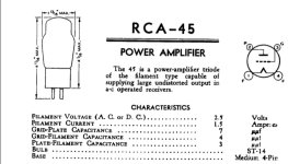
My friend who owns an audio shop acquired a Shiny Eyes SET 45 amp and told me one of the channels was weaker than the other and the tube was not warming up.
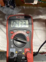
I told him I would take the unit home and do some testing to see if I could fix it. I plugged the unit in and immediately realized one channel was able to be biased right at 2.5VDC while the other could not get past 2VDC.
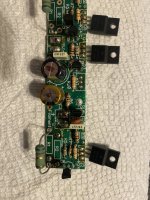
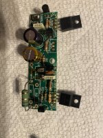
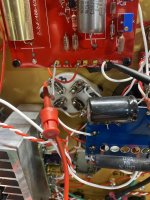
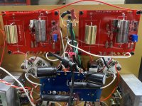
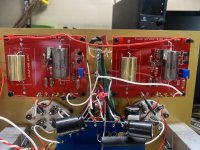
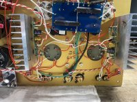
I looked inside and found the unit uses 2 Rod Coleman V7 regulator boards. What I found interesting is that the two boards did not have matching parts for R6 and R20; I am trying to determine the reasoning behind it.
I removed both boards and did some resistance checks.
-Not working left channel board
I had the parts on my bench and just finished swapping them out. I plan to put both regulators back on tonight but wanted to get some feedback first.
The board with the two brown dots on the caps is the left channel non working board.
I told him I would take the unit home and do some testing to see if I could fix it. I plugged the unit in and immediately realized one channel was able to be biased right at 2.5VDC while the other could not get past 2VDC.
I looked inside and found the unit uses 2 Rod Coleman V7 regulator boards. What I found interesting is that the two boards did not have matching parts for R6 and R20; I am trying to determine the reasoning behind it.
I removed both boards and did some resistance checks.
- Working Right channel board
- R6 is a 330 ohm resistor and matches the instruction manual
- R20 is a 1k ohm resistor and matches the instruction manual (says it should be 3.3k if supply is greater than 15V)
-Not working left channel board
- R6 is a 1k ohm resistor
- R20 is a 3.3k ohm
I had the parts on my bench and just finished swapping them out. I plan to put both regulators back on tonight but wanted to get some feedback first.
The board with the two brown dots on the caps is the left channel non working board.
Attachments


I have some larger high wattage resistors but what would be an appropriate value?
I’m guessing that resistor would go across the filament.
Yes. I removed all the dirty blobs of solder to put newer solder on when wiring everything back up.
I’m guessing that resistor would go across the filament.
Yes. I removed all the dirty blobs of solder to put newer solder on when wiring everything back up.
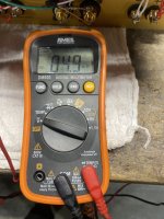
Just use Ohms law to get the appropriate resistor- eg 01a using 5V at 250mA would be simulated by ~20r resistor and just over 1W.
Once you know its working and delivering the voltage across the resistor (so it is delivering the current), then you can back it off a bit and install, hook up the tube, and then bring the voltage back up to target.
Once you know its working and delivering the voltage across the resistor (so it is delivering the current), then you can back it off a bit and install, hook up the tube, and then bring the voltage back up to target.
Looks correct except it's 1.5A not 1.25A. So if you used 1.68ohm, bring your voltage up to 2.5V, and it holds, chances are everything is ok. Then bring it back down a bit, say to 1.8-2V before swapping over to the amp. Then when connected there, bring it back up. I'd do a couple of checks after you have hv applied etc. but then you should be set.
Bear in mind 1.25A across 2.5V is over 3W so the resistor will get hot
Bear in mind 1.25A across 2.5V is over 3W so the resistor will get hot
Ok. I think that fixed the bias issue. I now can get both channels at 2.5V. Sound levels on both tubes sound equal on my bench speakers, but I still have the same issue where the left channel tube gets hotter than the right channel. I am not sure exactly how hot a 45 tube gets, but I noticed the right channel tube (the one that worked fine with bias before) only gets to 33 degrees Celsius while the left tube gets all the way up to 90 degrees Celsius.
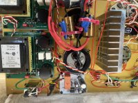
I did some testing at the Plate Girator board thinking it is the grid voltage and noticed:
Anode test to ground (looks pretty normal)
"Out" test to ground (from girator board to Pin 3 grid on the 45 tube)
I now know something is also wrong with one of these boards. Not sure I can find a schematic but can do some resistance checks between the two boards.
I did some testing at the Plate Girator board thinking it is the grid voltage and noticed:
Anode test to ground (looks pretty normal)
- Left channel is 213V
- Right channel is 221V
"Out" test to ground (from girator board to Pin 3 grid on the 45 tube)
- Left channel (hotter tube) gets up to -0.433V
- Right channel only gets to 4.9mv
I now know something is also wrong with one of these boards. Not sure I can find a schematic but can do some resistance checks between the two boards.
Attachments
Why no ask the Shiny Eyes original developer?
https://simplepleasuretubeamps.com/about/
Radu also member here.
https://simplepleasuretubeamps.com/about/
Radu also member here.
Is this direct coupled from gyrator Mu output to #45 grid (I do not think so), or capacitor coupled (on gyrator board 2.2uF)?"Out" test to ground (from girator board to Pin 3 grid on the 45 tube)
- Left channel (hotter tube) gets up to -0.433V
- Right channel only gets to 4.9mv
I now know something is also wrong with one of these boards. Not sure I can find a schematic but can do some resistance checks between the two boards.
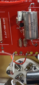
If it's the second, I don't see the #45 grid leak resistors (100k..330k from grid to ground) on your pictures.
If the grid leak omitted, or break, (static grid voltage not zero) the tube is unstable, or go bad.
I will pull and test the transistors. Which board seems to be the peoblem board based on measurements and heat?It seems very similar to Bartola hybrid mu-follower, I will check all transistors. Good lucky.
Should the 45 tube get up over 90 degrees Celsius? Keeping in mind the Mu out was only about 5mv. (Right channel)
Or does 35 degrees sound more like how the tube should operate? Which was -0.400mv. (Left Channel)
I’ve never owned a 45 amp so not sure how hot this tube should get after full warm up.
Good call. I couldn’t find his user name but I’ll see if I can contact him through his website.Why no ask the Shiny Eyes original developer?
https://simplepleasuretubeamps.com/about/
Radu also member here.
Let me take more pictures. The interesting thing is the 2 gold caps are actually .22uf and not 2.2uf.Is this direct coupled from gyrator Mu output to #45 grid (I do not think so), or capacitor coupled (on gyrator board 2.2uF)?
If it's the second, I don't see the #45 grid leak resistors (100k..330k from grid to ground) on your pictures.
If the grid leak omitted, or break, (static grid voltage not zero) the tube is unstable, or go bad.
https://www.diyaudio.com/community/members/abszero.231275/Good call. I couldn’t find his user name but I’ll see if I can contact him through his website.
p.s.
Are you read this?
https://simplepleasuretubeamps.com/2016/09/30/shiny-eyes-se-45/
I just sent him a direct email with a link to this thread. Thank you.
I was on this website but forgot to go back to his drawing. Let me take a look at it.
There is a 330k resistor here on the board.
I was on this website but forgot to go back to his drawing. Let me take a look at it.
There is a 330k resistor here on the board.
Attachments
Last edited:
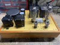
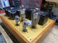
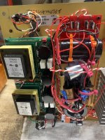
Here are pictures of the unit.
Attachments
-
 IMG_5305.jpeg357.9 KB · Views: 95
 -
 IMG_5308.jpeg327.8 KB · Views: 93
 -
 IMG_5307.jpeg356.6 KB · Views: 79
 -
 IMG_5306.jpeg274.5 KB · Views: 84
 -
 IMG_5309.jpeg435.2 KB · Views: 88
 -
 IMG_5310.jpeg380.6 KB · Views: 94
 -
 IMG_5311.jpeg415.8 KB · Views: 91
 -
 IMG_5312.jpeg331.2 KB · Views: 89
 -
 IMG_5313.jpeg398 KB · Views: 79
 -
 IMG_5314.jpeg397.3 KB · Views: 91
If you desolder both grid stopper resistors (100R?) from gyrator output and solder it to 100k resistors (100k other leg grounded), please measure theses:There is a 330k resistor here on the board.
1.) voltage on 330k resistors;
2.) voltage on 100k resistors;
3.) voltage on anodes;
4.) voltage on cathode resistors.
If each tube good, the 3.) and 4.) are similar values (within 10-15%).
If one of the voltage of 100k resistors ( 2.) ) not null (except few mV), this tube possible damaged.
If 1.) not null, this 0.22uF capacitor leaking.
p.s.
Possible schematic:

The estimated anode current about 32-35mA, so voltage on 1k5 cathode resistor is 48-52V.... if the tube working well.
Last edited:
A big thanks to @Abszero (Radu) for emailing me with the amp via email but I told him I would keep the update going here.
Here are the measurements with the 100k resistor from ground to the grid resistor (100 ohm). I swapped both tubes after the first measurement to be sure I got close to the same results.
Biggest discrepancies are across the 100k and the Cathode resistor.
Left Channel (channel with tube that gets really hot over 90 degrees celsius)
- across the 330k = 0mv
- across the 100k = -.537V
- Anode = 216V
- Cathode = -4.9mv
Right Channel (channel with tube around 35 degrees celsius)
- across the 330k = 0mv
- across the 100k = 0mv
- Anode = 222V
- Cathode = 39.5V
"Left Channel (channel with tube that gets really hot over 90 degrees celsius)
- across the 330k = 0mv
- across the 100k = -.537V
- Anode = 216V
- Cathode = -4.9mv "
If it's real, this tube not working (shorted cathode complex?).
This saturated tube reduces B+, therefore good channel anode voltage is near 220V, instead of about 290V (if B+ is 300V).
Is cathode capacitor good (not shorted)? Remove it, for DC testing it's unnecessary.
Is cathode resistor really 1k5?
Try to connect 10R between anode and OPT secondary, and measure voltage on it.
If it differs from another channel (significantly exceeds 40-50mA) the tube possible defected.
- Home
- Amplifiers
- Tubes / Valves
- Shiny Eyes 45 Regulator Issues - Rod Coleman V7