When I install fets the highside half of the 21844s chips gets damaged. It happens to both chips. I say this because the readings on the lowside don't change after the damage.
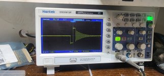
Without fets the signal on the low side is good until I try installing fets
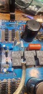
The card is a ZNCM_HP and worked fine in a similar amp so the problem is definitely on the main board
Without fets the signal on the low side is good until I try installing fets
The card is a ZNCM_HP and worked fine in a similar amp so the problem is definitely on the main board
Is the feedback resistor within tolerance?
^^^ Resistor between high-side source terminal and the negative terminal of the high-side B+ supply.
How many ICs have been damaged?
Have you tried powering it with low rail voltage?
Which pins on the high-side of the damaged ICs read different after they fail?
^^^ Resistor between high-side source terminal and the negative terminal of the high-side B+ supply.
How many ICs have been damaged?
Have you tried powering it with low rail voltage?
Which pins on the high-side of the damaged ICs read different after they fail?
Upon further inspection it appears lowside on both and the highside of 1 chip were damaged.
Let me reword that
1 chip was damaged both high and lowside
The other chip only the lowside. Pins 5-7 showed damage. I have a working card to base this off of.
Let me reword that
1 chip was damaged both high and lowside
The other chip only the lowside. Pins 5-7 showed damage. I have a working card to base this off of.
I don't think I have a diagram for this amp.
How is that resistor being used? Directly across the output? In series with the cap and both across the output?
What signal do you see on the terminals of the resistor?
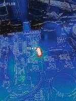
What FLIR are you using? That's an impressive image (level of detail).
How is that resistor being used? Directly across the output? In series with the cap and both across the output?
What signal do you see on the terminals of the resistor?
What FLIR are you using? That's an impressive image (level of detail).
It is connected to the speaker negative and final output inductor.
Using the common ground as a reference I get neg rail on the inductor side and 0v on the speaker neg side.
Yes it's connected to the capacitors
It's a flir one and it has helped me locate so many problems I didn't even know were there. It's been a very useful piece of equipment. It was less than $200
Do you know for a fact that the resistor should be a 100 ohm? If it's connected as you stated, I'd expect it to be more in the range of 2.2k to 2.7k.
If you have negative rail on the inductor, the driver board isn't working as it should.
Do you see pulses from any of the outputs of the driver board?
If you have negative rail on the inductor, the driver board isn't working as it should.
Do you see pulses from any of the outputs of the driver board?
I have a working card but I'm scared to put it in and have it not work anymore. Both cards worked on the other amp the other day. I feel like it's on the main board but doesn't show itself without a card in.
If it's again damaged, posting the pins that short or leak (compared to a new IC) could help lead to the problem area on the main board.
I was correct. Both cards still work fine in the other amp. Something about putting the card in is doing it but it's not on the card.
Have you tried disabling one driver IC at a time to see if you could determine if the problem (on the main board) was with one or the other?
Did you confirm that the resistors that connect the high-side source terminal to the VS terminal on the 21844s were within tolerance?
Is the 12v regulator capable of driving a load (try a resistor of about 20 ohms, will need to be about 5w)? Alternately, you can use a 12v lamp to test it. Just test the regulator for a few seconds so it doesn't overheat.
Last edited:
- Home
- General Interest
- Car Audio
- Zenon 8k highside issue