Hey,
i have a problem with the esx qe 900.4.
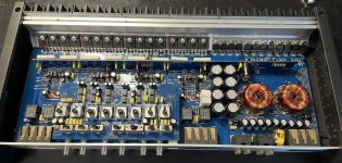
I replaced the power supply fets (IRF3205, the original ones were other fets), gate resistors to 47ohm and the corresponding 8 SMD transistors for controlling the power supply fets.
Also channel 3 output fets, TIP35CW and TIP36CW, because the batch was completely different. (someone has already tried to repair it)
Amp works, rail voltage +- 42v also fits, all channels play music/sine without problems and without distortion.
The problem is the constantly increasing current. Good to see on the laboratory power supply unit.
At 14.4V it is 2.3A idle current. Then the current slowly increases, normally not a problem when the amp warms up and bias sets. But it does not stop drawing current. After 15 min the idle current is already at 4,2A. In my opinion, that is far too much. Music continues play without problems. The amp does not get very hot, except the MJE340g and MJE350g. output fets and ps fets are all within the normal temperature range.
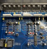
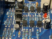
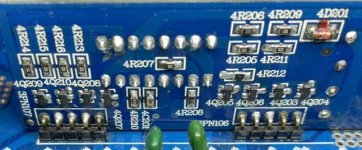
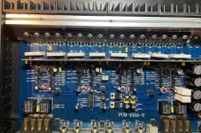
Unfortunately i have no idea how to set the bias on these amps, or rather i assume that bias is set "automatically" here. (bias-circuit in the photos)
Does anyone have any idea what is slowly but steadily drawing current here? If I set the voltage to 11v or 12v, it holds it for a while, but then also rises, only more slowly.
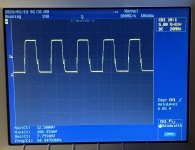
(I am still surprised that the oscillation frequency of the power supply is 52khz and not ~25khz as usual)
i have a problem with the esx qe 900.4.
I replaced the power supply fets (IRF3205, the original ones were other fets), gate resistors to 47ohm and the corresponding 8 SMD transistors for controlling the power supply fets.
Also channel 3 output fets, TIP35CW and TIP36CW, because the batch was completely different. (someone has already tried to repair it)
Amp works, rail voltage +- 42v also fits, all channels play music/sine without problems and without distortion.
The problem is the constantly increasing current. Good to see on the laboratory power supply unit.
At 14.4V it is 2.3A idle current. Then the current slowly increases, normally not a problem when the amp warms up and bias sets. But it does not stop drawing current. After 15 min the idle current is already at 4,2A. In my opinion, that is far too much. Music continues play without problems. The amp does not get very hot, except the MJE340g and MJE350g. output fets and ps fets are all within the normal temperature range.
Unfortunately i have no idea how to set the bias on these amps, or rather i assume that bias is set "automatically" here. (bias-circuit in the photos)
Does anyone have any idea what is slowly but steadily drawing current here? If I set the voltage to 11v or 12v, it holds it for a while, but then also rises, only more slowly.
(I am still surprised that the oscillation frequency of the power supply is 52khz and not ~25khz as usual)
Attachments
Measuring on the legs of the output transistors (those directly connected to the emitter resistors), do you see one channel increasing more than the other channels?
Are you 100% sure that the TIP35/36 were the original part number parts?
Are you 100% sure that the TIP35/36 were the original part number parts?
Idle has to be below 2A to avoid thermal prot kicking in the car when amp is pushed hard. I am not sure the pwn drive circuit can drive 3205s. In one instance i had to install a small pcb with a higher current drive for the power supply fets. The entire amp is designed marginally
i confirm tip35/36 are the original parts (the TO-247 type, not TO-218). For the power supply the original fets are irfz44 with 100R gate resistors.
Pretty sure. The soldering points look original and the tip35/36 too. I only changed the transistors of channel 3.Are you 100% sure that the TIP35/36 were the original part number parts?
I'll try again in a moment, but I'm sure I haven't seen anything like this.Measuring on the legs of the output transistors (those directly connected to the emitter resistors), do you see one channel increasing more than the other channels?
I am not sure the pwn drive circuit can drive 3205s
of course that could be. i think i have read that the irf3205 should fit. but i could be wrong.
Ultra:
Is the amp going into thermal protection because the bias isn't holding?
Or because the heatsink is too small?
Bombalamateia:
Do you have a scope?
The bias can probably be adjusted with the change of the value of one resistor per channel.
Is the amp going into thermal protection because the bias isn't holding?
Or because the heatsink is too small?
Bombalamateia:
Do you have a scope?
The bias can probably be adjusted with the change of the value of one resistor per channel.
I have a scope, running right now 😀
CH1: .009mV DC
CH2: .045mv DC
CH3: .015mV DC
CH4: .014mV DC
Channel 2 is the only difference i can see on the scope when measuring output transistor emitter to each other.
CH1: .009mV DC
CH2: .045mv DC
CH3: .015mV DC
CH4: .014mV DC
Channel 2 is the only difference i can see on the scope when measuring output transistor emitter to each other.
Ultra:
Is the amp going into thermal protection because the bias isn't holding?
Or because the heatsink is too small?
The bias can probably be adjusted with the change of the value of one resistor per channel.
Both. I had to modify the bias so there was some crossover distortion at 10KHz in order to keep it from overheating. Still, at 2 ohm loads it overheated. Then i put a fan inside the amp. I repaired 3 or 4 of these korean made amps and all had issues.
Bombalamateia:
As the amp heats up, does one of the 4 channels have a bigger increase in the voltage across the emitter resistors than the others?
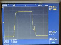
Post a scope cap of the waveform on the gate leg (on the leg) of one FET (assuming that all are the same).
Ultra:
Did you try moving the bias transistor into thermal contact with the output transistors?
Did you try going to a transistor with higher gain (hFE)?
As the amp heats up, does one of the 4 channels have a bigger increase in the voltage across the emitter resistors than the others?
Post a scope cap of the waveform on the gate leg (on the leg) of one FET (assuming that all are the same).
Ultra:
Did you try moving the bias transistor into thermal contact with the output transistors?
Did you try going to a transistor with higher gain (hFE)?
Did you calculate the oscillator frequency for the PS driver IC to see if the frequency was right for the timing components?
What are the part numbers for the PS driver transistors?
What are the part numbers for the PS driver transistors?
No.Did you calculate the oscillator frequency for the PS driver IC to see if the frequency was right for the timing components?
What are the part numbers for the PS driver transistors?
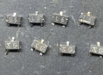
The original were
L6 - 2SC1623
SG - 2SA1162
The new ones are:
1GM - MMBTA06
2GM- MMBTA56
Attachments
Last edited:
Scope cap = screen cap (either direct from the scope or a photo like you posted).
Calculate the frequency to confirm that the frequency matches the timing components.
Calculate the frequency to confirm that the frequency matches the timing components.
To confirm and calculate i have to solder out Ct capacitor and measure it, right ? Rt is 4,7kOhm and the frequency is know, so i can calculate what value the capacitor should have.
Sorry Perry, I've never had to do it before.
Sorry Perry, I've never had to do it before.
It's a bit risky to remove the SMD cap (didn't realize it was SMD) but, worst case scenario, you replace it with the value that gets you back to where you are now (frequency).
You'd use the cap and resistor values to calculate the expected on-board reference oscillator frequency (frequency on the timing capacitor).
What driver IC is it using?
Did you heat the amp up again to see if all channels had an increase in emitter resistor voltage or if it was just one channel?
You'd use the cap and resistor values to calculate the expected on-board reference oscillator frequency (frequency on the timing capacitor).
What driver IC is it using?
Did you heat the amp up again to see if all channels had an increase in emitter resistor voltage or if it was just one channel?
No i didnt. I just lowered bias. Reading on reducing oscillating frequency, rang a bell, i think i also did thatDid you try moving the bias transistor into thermal contact with the output transistors?
Did you try going to a transistor with higher gain (hFE)?
its been a long time but yes, Fosc was around 50K I think i changed it to around 32KHz. There was a 1n smd timing capacitor that i changed to 1n2 or 1n5.
TL494What driver IC is it using?
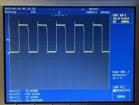
I reduced the oscillator frequency to 25k with 10N and 2.2k resistor. Calculated 25k and it is 25k.
But still getting hot.
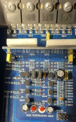
Channel 1 is raising up. Especially the TIP35C. They had different batches...Did you heat the amp up again to see if all channels had an increase in emitter resistor voltage or if it was just one channel?
You can clearly see that transistor pairs with different batches have more bias voltage here.
Channel 2, 3 and 4 have new MJE340/350. There were not enough parts left for channel 1.
I think have to change on Channel 1 the TIP35/36 same batch and MJE340/350 too ?
Attachments
- Home
- General Interest
- Car Audio
- ESX Quantum QE 900.4 continuously draw current