I just built 20 high quality composite chipamp (class AB) amplifier boards but only really need 10 and would like to sell the extras. These are my version 5 (sigh) but they're finally pretty good and what with high fixed-costs I decided to build more than I need.

Contents: completed and tested amplifier board(s)
Not included: power supply ; heatsinks; case
Price: $50 each (minimum of two). Free shipping CONUS.
Options: with a small ballast resistor they can run in parallel or bridged for higher power or lower impedance or better heat dissipation
SPECS: balanced inputs, up to about 40WRMS@8 or 60WRMS@4 ohms depending on power supply. At higher power the distortion specs don't change much other than better S/N.
POWER REQUIREMENTS: +-22 up to +-40V. Higher voltages are 8 ohm only unless paralleled amps. The amp voltage swing is a bit less than the power supply. The measurements are remarkably consistent between samples and very good but not guaranteed identical. Higher voltages generate a lot more heat. At +-25VDC it's a 40W@4 amp.
Here's the first sample's 5W@4 ohms. Here I'm powering it with 2 bridged Meanwell LRS-150-24 power supplies @25VDC. A linear supply would be slightly quieter. This was unbalanced input and the output choke hasn't been glued together yet 🙂 ->

I'll add more detail if requested. Warranty: it's tough to warranty something you can destroy by powering backwards or ... but I guarantee I will test/validate them before ship and include a printout of 5W@4 result for the board itself that should look much like this.
I've attached the REW file with my first tests. Note that the dynamic range of the amps is more than my test equipment so I have to test higher powers (>5 Watts) with a voltage divider which adds noise. I mark those as -6 or -10 (6db or 10db dividers).
My personal opinion is that these sound better than any amplifier I've ever owned. I listen to music at moderate sound levels on fairly efficient speakers. I use 4 of these amplifiers per channel (two in parallel for 4ohm woofer, one mid, one tweeter) in a DSP amplifier setup (so 8 total for stereo) - hence the need for 10.
Mark
Contents: completed and tested amplifier board(s)
Not included: power supply ; heatsinks; case
Price: $50 each (minimum of two). Free shipping CONUS.
Options: with a small ballast resistor they can run in parallel or bridged for higher power or lower impedance or better heat dissipation
SPECS: balanced inputs, up to about 40WRMS@8 or 60WRMS@4 ohms depending on power supply. At higher power the distortion specs don't change much other than better S/N.
POWER REQUIREMENTS: +-22 up to +-40V. Higher voltages are 8 ohm only unless paralleled amps. The amp voltage swing is a bit less than the power supply. The measurements are remarkably consistent between samples and very good but not guaranteed identical. Higher voltages generate a lot more heat. At +-25VDC it's a 40W@4 amp.
Here's the first sample's 5W@4 ohms. Here I'm powering it with 2 bridged Meanwell LRS-150-24 power supplies @25VDC. A linear supply would be slightly quieter. This was unbalanced input and the output choke hasn't been glued together yet 🙂 ->
I'll add more detail if requested. Warranty: it's tough to warranty something you can destroy by powering backwards or ... but I guarantee I will test/validate them before ship and include a printout of 5W@4 result for the board itself that should look much like this.
I've attached the REW file with my first tests. Note that the dynamic range of the amps is more than my test equipment so I have to test higher powers (>5 Watts) with a voltage divider which adds noise. I mark those as -6 or -10 (6db or 10db dividers).
My personal opinion is that these sound better than any amplifier I've ever owned. I listen to music at moderate sound levels on fairly efficient speakers. I use 4 of these amplifiers per channel (two in parallel for 4ohm woofer, one mid, one tweeter) in a DSP amplifier setup (so 8 total for stereo) - hence the need for 10.
Mark
Attachments
Last edited:


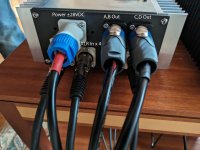
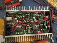
Here's the (first version) 4-channel amp wired up and running a 3-way speaker. The S/N ratio is 101dB (rounding up). Note 5W@8 and 10W@4 and above measurements go through a resistive divider which reduces the S/N ratio by 3dB or so..
The power wiring here is causing the THD of the top right amp to nearly double from 0.0011 to 0.0018 at 5W@4 but the S/N is unchanged at 101. B2 is after moving the wiring out 1/2 inch. The enclosure is a bit tight for running wire and general maintenance. Next enclosure will be slightly wider.
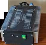
The enclosure is 10"x5"x3" internally - and I caught the SpeakOn mistake.
The power wiring here is causing the THD of the top right amp to nearly double from 0.0011 to 0.0018 at 5W@4 but the S/N is unchanged at 101. B2 is after moving the wiring out 1/2 inch. The enclosure is a bit tight for running wire and general maintenance. Next enclosure will be slightly wider.
The enclosure is 10"x5"x3" internally - and I caught the SpeakOn mistake.
Attachments
Last edited: