Hello to all!
I'm designing an amplifier using TDA2050. I took this project as a basis:
https://www.circuitbasics.com/tda2050-diy-amplifier-build-guide/#The-Zobel-Network
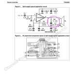
It uses a combination of 10 Ohm + 0.1 µF. However, the datasheet for the TDA2050 recommends 2.2 Ohm + 0.47 µF.
Questions:
1) Does the difference in denominations have any practical significance?
2) Where should Zobel Network be located, before or after the 2-way crossover? And if after it, then do I need two networks (one for tweeter and one for woofer)?
Thanks!
I'm designing an amplifier using TDA2050. I took this project as a basis:
https://www.circuitbasics.com/tda2050-diy-amplifier-build-guide/#The-Zobel-Network
It uses a combination of 10 Ohm + 0.1 µF. However, the datasheet for the TDA2050 recommends 2.2 Ohm + 0.47 µF.
Questions:
1) Does the difference in denominations have any practical significance?
2) Where should Zobel Network be located, before or after the 2-way crossover? And if after it, then do I need two networks (one for tweeter and one for woofer)?
Thanks!
Obviously it must be located before the crossover, otherwise it won't work.
The Zobel network increases stability at high frequencies and can help to stop oscillation at HF.
Different values meet the needs for different output impedances.
The Zobel network increases stability at high frequencies and can help to stop oscillation at HF.
Different values meet the needs for different output impedances.
Attachments
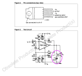

It serves to ensure the amp sees a fairly constant resistive (not reactive or open) load at high frequency (100's of kHz and up) - reactive loads direct on a feedback amp can destabilize the loop. Thats also why there is usually an air-cored inductor after the Zobel to isolate the amp from capacitance of the cable / crossover.
In any case, use whatever the chip designer suggests, "he" should know best, shouldn't he?
I have seen chipamps where datasheet suggestion is 1 ohm in series with .1uF or .22uF .... there must be some reason for that.
Who am I to outsmart designer?
Some chipamps have both very high open loop gain, high NFB and high bandwidth, so are fussy about the real world loads.
Maybe "classic" 10 ohm resistive component is not enough.