Hi, I'm trying to take a 1.5v audio signal and split it to 2 outputs, one with the phase inverted at 1.5v and one non inverted at 1.5v
I currently know two ways of doing this, the first is using a opamp chip with two comparators to make the circuit below. I have tested this and it works OK.

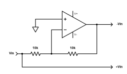
Vin is where audio signal comes in. A dual opamp is used as it has the two comparators needed to make this circuit. I used 10k on each resistor and it worked ok, a little background noise
Note that load is taking one inverted input and one non inverted input (from output of each comparator)
The other way which I have not tested is by using a single transistor and a resistor network to split phase, would this work as well as an op amp?

I currently know two ways of doing this, the first is using a opamp chip with two comparators to make the circuit below. I have tested this and it works OK.
Vin is where audio signal comes in. A dual opamp is used as it has the two comparators needed to make this circuit. I used 10k on each resistor and it worked ok, a little background noise
Note that load is taking one inverted input and one non inverted input (from output of each comparator)
The other way which I have not tested is by using a single transistor and a resistor network to split phase, would this work as well as an op amp?
Yes, as long as the external load is high enough, especially on the collector side!would this work as well as an op amp?
Notice that frequency related 'items' can pop up - there are hidden poles and zeros lurking to ruin these phase splitters into hf oscillators, discrete and opamp composed alike. Have a thourough analysis/ simulation processed in advance to capture these traps.
Just use the input signal as the positive part of the balanced output.
Also connect the input signal to an inverting op amp with unity gain, giving the negative part of the balanced output.
No need for a bridging resistor at all.
For most purposes, this will work just fine, with no need for coupling capacitors.
Note that a comparator is not an op amp, but rather a "digital" circuit that has only two output levels, high and low.
Attachments
Last edited:
Thanks for the reply. Sorry, my dual comparator phase splitter circuit diagram is incorrect, there isn't a resistor bridging the inverted and non inverted.
Inverted output is going to one amplifiers input(has a max input voltage of 1.5v) , and non inverted is going to a different amplifiers input.
That diagram you sent is perfect. I don't have a comparator as a component itself, so I assume I can make use of one of the comparators in the op-amp.
Inverted output is going to one amplifiers input(has a max input voltage of 1.5v) , and non inverted is going to a different amplifiers input.
That diagram you sent is perfect. I don't have a comparator as a component itself, so I assume I can make use of one of the comparators in the op-amp.
The phase splitter will have the inverting input going to a irs2092s 500w mono amplifier
The non inverting will also go to a seperate irs2092s 500w mono amplifier. Each amplifiers positive audio output terminal goes to one subwoofer, which is why one amp needs an inverted input and one amp needs a non inverted input
I'm not sure about bandwidth, sorry.
I am going to be using tl072 as my op amp( the single comparator in it) or Is there a better suited op amp?

Because it's unity gain, the voltage I supply the tl072 with won't effect the inverted signal output voltage right? It's also got max of 1.5v because the input is 1.5v
- Home
- Source & Line
- Analog Line Level
- 1.5v Phase splitter