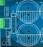
Aim; I want to have more capacitance
Some info
1. Only board1 has a rectifier bridge. This means AC is only going Too this board.
2. board2 (± V and ground pins on the missing rectifier) is connected to the corresponding locations in board1 immediately after the bridged rectifier
3. The boards are on top on each other using hex spacers.
4. This is what the input looks like.

Would it work? I thought of having rectifiers on both boards and then they share the transformer secondaries but I read that's bad idea.
Thanks for the help.
Some info
1. Only board1 has a rectifier bridge. This means AC is only going Too this board.
2. board2 (± V and ground pins on the missing rectifier) is connected to the corresponding locations in board1 immediately after the bridged rectifier
3. The boards are on top on each other using hex spacers.
4. This is what the input looks like.

Would it work? I thought of having rectifiers on both boards and then they share the transformer secondaries but I read that's bad idea.
Thanks for the help.