Hello !
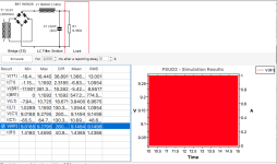
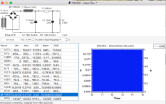
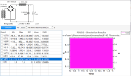
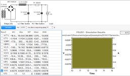
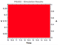
Looking at powering a tube filament via regulator I tried single section LC as well as LCRC. The filament is 4V/1.1A and the filament regulator is constant current with operating voltage of 3V expected, for a total of 7VDC.
I did the simulations with both CCS and also with an equivalent resistor (7V/1.1A=6.36Ω).
Both gave drop across the second section's 0.1Ω resistance much greater than I'd thought were realistic , near 3V in the case of the resistive load and 5 volts in the case of the CCS. Even at 10 times a simple IR drop it would only be 1V.
Surely the results can't be quite right, or can they?
Thanks
Attachments
It's a choke input filter, so it's possible that the choke's inductance is at the edge critical thereby varying the output voltage depending on current through it. Try increasing the inductance and see what happens.
You should increase the width of each section of the numerical results table so that the complete numbers and units are visible. Then the full picture may become apparent.
One possibility is that with the large 22mF capacitors, they have not fully charged after 10s - just a guess.
One possibility is that with the large 22mF capacitors, they have not fully charged after 10s - just a guess.
Your plot for resistive load shows 78.5mVrms across R1 under steady-state conditions, and 110mVrms with CCS load Did you think you were seeing near 3V or more ?I did the simulations with both CCS and also with an equivalent resistor (7V/1.1A=6.36Ω).
Both gave drop across the second section's 0.1Ω resistance much greater than I'd thought were realistic , near 3V in the case of the resistive load and 5 volts in the case of the CCS. Even at 10 times a simple IR drop it would only be 1V.
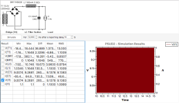
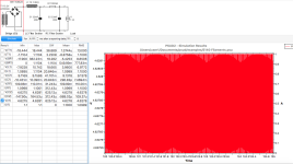
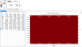
Well, perhaps I'm interpreting the results incorrectly but. . . . I am interested in the voltage across the load as the sim is meant to be for a 1.1Amp load that is a series combination of regulator that needs 3 Volts above the tube filament that it feeds , running at voltage of 4V.
So looking at either pair (resistive load or CCS) of sims in post #1 , the LCRC version has the load at a voltage lower than can be explained by a drop across the additional 0.1Ω RC filter section. That's what I think I see and that's what my question is about. If my understanding of the result is incorrect , I'd be more than happy to hear about it !
Thanks !!
Attachments
Last edited:
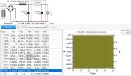
Thanks for the extra explanation. I can see why you are bemused by the PSUD2 results now. I can only say that you have entered into the wonderful world of simulations where the existing code is being pushed beyond its initial scope of use, and is not able to adequately calculate for that level of LCRCR complexity and parameter configuration, I would suggest that you simplify the circuit to just an LCR filter-load, and use the voltage across the R as the voltage being presented to your regulator input.
The datasheet for your reg may show input-to-output voltage drop for set levels of pass current, and you indicate that as 3V drop for 1A. So your sim, with just LCR, shows a feed voltage across 22mF would ultimately reach 8.9V, which is sufficient for your application (4V + 3V). Given you are using a regulator, I doubt there is any design merit in interposing an additional RC filter stage (or for that metter to use 22mF for starters), given the ripple attenuation likely achieved by the regulator. But caution is needed to measure your actual result, as the parameters you have used in PSUD may not be accurate, and PSUD assumes that parts are 'linear', and that the mains voltage waveform has no distortion, which could align to reduce the feed voltage into the regulator to dynamically fall below 7V, which could then appear as ripple across your filament.
The datasheet for your reg may show input-to-output voltage drop for set levels of pass current, and you indicate that as 3V drop for 1A. So your sim, with just LCR, shows a feed voltage across 22mF would ultimately reach 8.9V, which is sufficient for your application (4V + 3V). Given you are using a regulator, I doubt there is any design merit in interposing an additional RC filter stage (or for that metter to use 22mF for starters), given the ripple attenuation likely achieved by the regulator. But caution is needed to measure your actual result, as the parameters you have used in PSUD may not be accurate, and PSUD assumes that parts are 'linear', and that the mains voltage waveform has no distortion, which could align to reduce the feed voltage into the regulator to dynamically fall below 7V, which could then appear as ripple across your filament.
PSUD2 is all about simplifying computor calculations to minimise the programming and application size - and with that in mind, there are many well-meaning short-cuts taken to calculating voltages and currents. And it does that exceedingly well, and only rarely generates results that are not valid.
In contrast, commercial applications like LTSpice, PSpice etc are all about trying to make the simulation as close to 'real' as possible, but even they fall short for some aspects. And if you go down that path then be aware of the effort needed, even though there are forums and tutorials and multitudinous part databases to 'help'.
In contrast, commercial applications like LTSpice, PSpice etc are all about trying to make the simulation as close to 'real' as possible, but even they fall short for some aspects. And if you go down that path then be aware of the effort needed, even though there are forums and tutorials and multitudinous part databases to 'help'.
Hi and thanks.
I don't usually do sims of either sort. My inclination on getting an idea to try is simply to build it and see. But in this case I was hoping PSUD would help me figure out if I could verify a statement somebody made with parts I already have.
In PSUD, with the simple LC filter the dissipation in the regulator ended up higher than necessary so I started noodling around with values for an added filter section to take it down a bit.
Surprised at the resulting drop from added resistance ( I started at 2Ω ) things made even less sense as resistance was reduced and that sparked the question. Was it some law of rectification physics I didn't know or the personality of PSUD ?
'Trouble is that sim results look authoritative to me (Even EE's use PSUD, right?) and when they are at odds with what I know from my own experience I get stuck trying to figure out why. Your posts helped.
Thanks again!
- Home
- Amplifiers
- Power Supplies
- PSUD: Voltage Drop on added filter section