This is a German to English translation of @Gaga guide to ABEC from diy-hifi-forum in the EU
Also be sure to read this after-the-fact: https://www.diyaudio.com/community/threads/abec-experts-help.315353/
"Hello,
as the title suggests and there is obviously interest - the 'How-To Thread' about ABEC .
In the first attempt, 3eepoint (3D-CAD), Fabian, nailhead and Nils kindly contributed their know-how or agreed to do so during the course of the thread. We'll definitely need their input as soon as things get a little more complex... I won't be able to do this alone.
As I already said, I can now handle AkAbak to some extent and am now working on ABEC in order to be able to carry out somewhat more complex simulations in the future.
There is a free version of ABEC that is fully functional, but only cannot save the solving results. So anyone can get started easily and for free. Jörg Panzer even offers a ' student license' for ABEC for non-commercial use .
The plan is initially to simulate a simple BR box based on a demo file supplied with ABAC (the SP38 script). There is also a PDF document for simulating the SP38 BR box on the Randteam homepage under Studies . The aim is to learn the basic structure and basic functions of ABEC using a simple example. Your own model will be based on the small test BR box used in the Pc0 thread , so that the ABEC simulation results can be compared with both measurements and simulations from other programs. Of course, ABEC is not needed to simulate a BR speaker. But the possibility of importing housings drawn in 3D CAD programs into ABEC offers great possibilities for simulating horns, waveguides, etc.... What can be done with ABEC is also nice in Nils' thread ' Waste product with Quasikoax ' or in DIY Auido Forum ( Synergy Horn Thread ). Now let's go, round 2... Nevertheless, you should have the help file at hand for the first steps, which can also be downloaded individually. Greetings, Christopher
Attachments

Hello everyone,
as announced, I want to start with the first steps. First of all super simple with tiny steps.
On the one hand, this is pleasant for me as a beginner, but on the other hand, I hope that it alleviates some of the anxiety of other interested parties. So, don't run away because of it. I ask users with ABEC experience to take a look at the scripts from time to time and correct them if necessary.
As mentioned in the first post, 3ee and I first try to simulate a very simple BR test box
.
The housing dimensions are:
148mm x 297mm x 200mm (W x H x D) outside.
The bass (CP-104) is mounted 92mm from below (chassis center).
I will initially do this using scripts, 3ee using 3D CAD files that can be imported into ABEC.
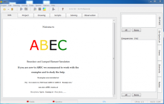
I assume that you have installed and loaded the program and the help and example files.
After starting ABEC you are greeted warmly by the start screen
In my opinion it makes sense to open the examples and just take a look. The scripts that I initially work with are roughly based on the example 'Speaker Cabinet SP38' (C:\xxx\RDTeam\ABEC3\ABEC3 Examples\BEM\Loudspeakers\Speaker Cabinet SP38).
However, I would like to describe the creation of a BEM script in detail, especially the creation of the housing from 'Nodes' and 'Elements'. I would be happy if someone would like to simulate their own BR box with the associated driver in parallel.
But how do you create your own simulation?
More on that in the next post...
Greetings,
Christoph
as announced, I want to start with the first steps. First of all super simple with tiny steps.
On the one hand, this is pleasant for me as a beginner, but on the other hand, I hope that it alleviates some of the anxiety of other interested parties. So, don't run away because of it. I ask users with ABEC experience to take a look at the scripts from time to time and correct them if necessary.
As mentioned in the first post, 3ee and I first try to simulate a very simple BR test box
.
The housing dimensions are:
148mm x 297mm x 200mm (W x H x D) outside.
The bass (CP-104) is mounted 92mm from below (chassis center).
I will initially do this using scripts, 3ee using 3D CAD files that can be imported into ABEC.
I assume that you have installed and loaded the program and the help and example files.
After starting ABEC you are greeted warmly by the start screen
In my opinion it makes sense to open the examples and just take a look. The scripts that I initially work with are roughly based on the example 'Speaker Cabinet SP38' (C:\xxx\RDTeam\ABEC3\ABEC3 Examples\BEM\Loudspeakers\Speaker Cabinet SP38).
However, I would like to describe the creation of a BEM script in detail, especially the creation of the housing from 'Nodes' and 'Elements'. I would be happy if someone would like to simulate their own BR box with the associated driver in parallel.
But how do you create your own simulation?
More on that in the next post...
Greetings,
Christoph
Attachments
"Hello,
how can you load information about the ABEC project so that it is displayed under the 'Info' tab?
By clicking on the 'Project' tab, you can create a project, i.e. load scripts that describe the project and tell ABEC how and what should be simulated: The individual scripts and files that can be loaded here

or need to do more, step by step.
First, the information about your own ABEC project: The information text about the project can be loaded by double-clicking on 'Information File'. A document window opens and ABEC now wants to load the information text. ABEC expects a text file in .rtf format here.

In this case, I simply wrote the text in Word and
saved the file as an RTF document in the ABEC project folder.
After the rtf file has been loaded, it appears in the project window:

...and of course also in the info window:

In principle, this works the same way with the BEM, LEM and observation scripts that we need to describe an ABEC project . However, these scripts must be loaded in .txt format and can be opened and modified at any time in ABEC by double-clicking...
In the next step, move on to the Boundary Element (BEM) script. What's in there? We'll see in the next post...
Greetings,
Christoph
how can you load information about the ABEC project so that it is displayed under the 'Info' tab?
By clicking on the 'Project' tab, you can create a project, i.e. load scripts that describe the project and tell ABEC how and what should be simulated: The individual scripts and files that can be loaded here
or need to do more, step by step.
First, the information about your own ABEC project: The information text about the project can be loaded by double-clicking on 'Information File'. A document window opens and ABEC now wants to load the information text. ABEC expects a text file in .rtf format here.
In this case, I simply wrote the text in Word and
saved the file as an RTF document in the ABEC project folder.
After the rtf file has been loaded, it appears in the project window:
...and of course also in the info window:
In principle, this works the same way with the BEM, LEM and observation scripts that we need to describe an ABEC project . However, these scripts must be loaded in .txt format and can be opened and modified at any time in ABEC by double-clicking...
In the next step, move on to the Boundary Element (BEM) script. What's in there? We'll see in the next post...
Greetings,
Christoph
Hi Patrick,
Very nice to see that you make use of the German ABEC-Thread and go here step by step as well. I'm happy to support as good as I can as well here.
I consider to start a comparable 'The AKABAK-Thread' on the German forum later this year - as soon as they change to a new version of the forum software (want to avoid issues and possible losses during the upcoming change). May be we can do this in parallel, if you're interested to support the thread here on DIY Audio.
With respect to the randteam-homepage: It still works, (see here), however, the old links might be broken as ABEC is no longer listed as a product there.
Best,
Christoph / Gaga
PS: You may ask Jörg Panzer (reandteam) for a ABEC download-link. This will include the help file refered to in the thread. I find ABEC3-downloads on the internet elswhere, however, I do not know if they are safe.
Last edited:
Hello Patrick/John,
The Randteam site does not seem to work...
kudos to @fluid for providing a new link : https://www.randteam.de/_Software/ABEC3_Pro/Download-ABEC-Pro.html
Here's a translation of Gaga's thread, this was post #4 from ten years ago:
Hi,
ABEC would like to know about the 'Boundary Element Script'
In later posts, 3ee will probably show how to draw an enclosure in a 3D CAD program and import it into ABEC. This will simplify some work at this point, or rather make it unnecessary, and greatly expand the possibilities of ABEC simulations. Until then, we'll continue on foot...
Like the 'Information File', the BEM script (txt file) can be loaded by double-clicking on 'Boundary Element Script':

The example BEM script for the CP-104 BR box is divided into two text documents, the 'Solving Script' and the 'Nodes Script'. This doesn't necessarily have to be the case; all the information could also be contained in a script.
First, the 'solving script,' here the part with the calculation instructions for ABEC. It's super simple in this example:
//************************************************** ***************************
//
// ABEC3 Solving File
// Project: CP104 Enclosure 1
//
//************************************** ***************************
// Reference to another text file in which the enclosure coordinates (nodes) are described
File="Nodes CP104 Enclosure 1.txt"
Control_Solver
f1=30; f2=2000;
NumFrequencies=60; Abscissa=log;
MeshFrequency=2000Hz
Sym=x
Meshing=Delaunay
A few small explanations:
Whenever the '//' characters appear before a line, the text is not read by the program – it consists of explanations and comments.
This script therefore contains very little:
The meaning of the individual parameters in the Control_Solver can be quickly and easily looked up in the help file
. Just take a look...

...look at the corresponding parameters and play with them.
Here:
f1=30; f2=2000; // Frequency range of the simulation
NumFrequencies=60; Abscissa=log; // Number of simulated frequencies
MeshFrequency=2000Hz // Resolution/fineness of the 'mesh' calculation
Sym=x // Enclosure symmetry to the x-plane (refers to the enclosure or Nodes script, more on this later).
Meshing=Delaunay //ABEC offers a choice between two meshing modes, 'Delaunay' and 'Bifu'. Delaunay is probably better at depicting complex shapes, but it requires more processing time. Don't ask me about the differences...

The next post will cover the description of the housing using 'nodes' and 'elements'.
Anyone else joining?
Regards,
Christoph
Hi,
ABEC would like to know about the 'Boundary Element Script'
- what the enclosure to be simulated looks like,
- what the driver to be simulated looks like,
- where the driver is installed in the enclosure,
- which frequency range and how finely it should be calculated, and
- whether and which enclosure symmetries are used when describing the enclosure.
In later posts, 3ee will probably show how to draw an enclosure in a 3D CAD program and import it into ABEC. This will simplify some work at this point, or rather make it unnecessary, and greatly expand the possibilities of ABEC simulations. Until then, we'll continue on foot...
Like the 'Information File', the BEM script (txt file) can be loaded by double-clicking on 'Boundary Element Script':
The example BEM script for the CP-104 BR box is divided into two text documents, the 'Solving Script' and the 'Nodes Script'. This doesn't necessarily have to be the case; all the information could also be contained in a script.
First, the 'solving script,' here the part with the calculation instructions for ABEC. It's super simple in this example:
//************************************************** ***************************
//
// ABEC3 Solving File
// Project: CP104 Enclosure 1
//
//************************************** ***************************
// Reference to another text file in which the enclosure coordinates (nodes) are described
File="Nodes CP104 Enclosure 1.txt"
Control_Solver
f1=30; f2=2000;
NumFrequencies=60; Abscissa=log;
MeshFrequency=2000Hz
Sym=x
Meshing=Delaunay
A few small explanations:
Whenever the '//' characters appear before a line, the text is not read by the program – it consists of explanations and comments.
This script therefore contains very little:
- A reference to the Nodes script "Nodes CP104 Enclosure 1.txt" and
- the Control_Solver, i.e., the calculation parameters.
The meaning of the individual parameters in the Control_Solver can be quickly and easily looked up in the help file
. Just take a look...
...look at the corresponding parameters and play with them.
Here:
f1=30; f2=2000; // Frequency range of the simulation
NumFrequencies=60; Abscissa=log; // Number of simulated frequencies
MeshFrequency=2000Hz // Resolution/fineness of the 'mesh' calculation
Sym=x // Enclosure symmetry to the x-plane (refers to the enclosure or Nodes script, more on this later).
Meshing=Delaunay //ABEC offers a choice between two meshing modes, 'Delaunay' and 'Bifu'. Delaunay is probably better at depicting complex shapes, but it requires more processing time. Don't ask me about the differences...
The next post will cover the description of the housing using 'nodes' and 'elements'.
Anyone else joining?
Regards,
Christoph
Post 5:
"I was thinking about describing a case using 'nodes' and 'elements' in detail, step by step. It might be rather boring for people who are familiar with ABEC, but I think it makes sense to start the thread.
In my experience, it's a good idea to first simply draw the case and its dimensions on a piece of paper and number the case corners (nodes). I did this once for the CP-104 test case:

In addition to the numbered case corners, I drew the case dimensions (148mm x 297mm x 200mm, W x H x D, external) and the spatial dimensions x, y, and z.
Since the case is symmetrical along the yz surface, i.e. the x-axis, I only drew half the case width. That's why the solving script says 'Sym=x'. Why so complicated? It saves computational effort and thus processing time, which can be quite useful later on, depending on the project.
What you can also see in the drawing is the order in which the vertices/nodes are numbered. This will be important later, when surfaces ('elements') are created from the vertices. I'll come back to this.
The list of nodes (node #, x, y, z, values in mm) is read from the drawing:
2001 74, 297, 0
2002 0, 297, 0
2003 0, 0, 0
2004 74, 0, 0
2201 74, 297, -200
2202 0, 297, -200
2203 0, 0, -200
2204 74, 0, -200
The node numbering could also be done with other numbers—but each number should uniquely describe a point, so it shouldn't be repeated in the node script.
In the node script, it would look like this:
//**************************************************** ****************************
//
// ABEC3 Nodes File
// Project: CP104 Enclosure 1
// Gaga 2015
//
//**************************************************** ****************************
// Symmetry-plane is yz (Sym=x)
// Front in xy-plane pointing along z-axis
// Height is 297mm (in y)
// Width is 74mm (in x)
// Depth is 200mm (in -z)
Nodes "N1"
Scale=1mm
// Node #, x, y, z
2001 74 297 0
2002 0 297 0
2003 0 0 0
2004 74 0 0
2201 74 297 -200
2202 0 297 -200
2203 0 0 -200
2204 74 0 -200
So, the only things that need to be added to the list are the information Nodes "N1" and Scale=1mm.
Scale=1mm must be specified if mm values are entered—otherwise, m is assumed.
The information Nodes "N1" is important because the housing surfaces ('Elements') are composed of the nodes and refer to a specific node list (here "N1").
After the nodes are defined—other housings could, of course, be described here—in the next post, we'll build the elements from the nodes, and from the elements, the CP-104 housing.
Regards,
Christoph
"I was thinking about describing a case using 'nodes' and 'elements' in detail, step by step. It might be rather boring for people who are familiar with ABEC, but I think it makes sense to start the thread.
In my experience, it's a good idea to first simply draw the case and its dimensions on a piece of paper and number the case corners (nodes). I did this once for the CP-104 test case:
In addition to the numbered case corners, I drew the case dimensions (148mm x 297mm x 200mm, W x H x D, external) and the spatial dimensions x, y, and z.
Since the case is symmetrical along the yz surface, i.e. the x-axis, I only drew half the case width. That's why the solving script says 'Sym=x'. Why so complicated? It saves computational effort and thus processing time, which can be quite useful later on, depending on the project.
What you can also see in the drawing is the order in which the vertices/nodes are numbered. This will be important later, when surfaces ('elements') are created from the vertices. I'll come back to this.
The list of nodes (node #, x, y, z, values in mm) is read from the drawing:
2001 74, 297, 0
2002 0, 297, 0
2003 0, 0, 0
2004 74, 0, 0
2201 74, 297, -200
2202 0, 297, -200
2203 0, 0, -200
2204 74, 0, -200
The node numbering could also be done with other numbers—but each number should uniquely describe a point, so it shouldn't be repeated in the node script.
In the node script, it would look like this:
//**************************************************** ****************************
//
// ABEC3 Nodes File
// Project: CP104 Enclosure 1
// Gaga 2015
//
//**************************************************** ****************************
// Symmetry-plane is yz (Sym=x)
// Front in xy-plane pointing along z-axis
// Height is 297mm (in y)
// Width is 74mm (in x)
// Depth is 200mm (in -z)
Nodes "N1"
Scale=1mm
// Node #, x, y, z
2001 74 297 0
2002 0 297 0
2003 0 0 0
2004 74 0 0
2201 74 297 -200
2202 0 297 -200
2203 0 0 -200
2204 74 0 -200
So, the only things that need to be added to the list are the information Nodes "N1" and Scale=1mm.
Scale=1mm must be specified if mm values are entered—otherwise, m is assumed.
The information Nodes "N1" is important because the housing surfaces ('Elements') are composed of the nodes and refer to a specific node list (here "N1").
After the nodes are defined—other housings could, of course, be described here—in the next post, we'll build the elements from the nodes, and from the elements, the CP-104 housing.
Regards,
Christoph
The previous post was post FOUR not five from the German thread: https://www.diy-hifi-forum.eu/forum...er-ABEC-Thread&p=153135&viewfull=1#post153135
Here's post five from the German thread: https://www.diy-hifi-forum.eu/forum...er-ABEC-Thread&p=153149&viewfull=1#post153149
"Hey,
ABEC assembles the housing surfaces ('elements') from the 'nodes', i.e., xyz-defined housing corners.
In the script, it looks like this:
Elements "Enclosure-Exterior"
RefNodes="N1"
SubDomain=1
101 2003 2203 2204 2004 // bottom wall
102 2203 2202 2201 2204 // rear wall
103 2002 2001 2201 2202 // top wall
104 2004 2204 2201 2001 // side wall
201 2003 2004 2001 2002 // baffle
It is defined
that: - the described 'elements' describe the exterior of the enclosure (elements "Enclosure-Exterior"). We can also describe the interior of the enclosure later...;
Why is this of interest to us? Not yet for the creation of the enclosure, but ABEC can define subdomains, such as the enclosure interior, the enclosure exterior (room), bass reflex tubes, the internal volume of horns, etc., and how they interact across the respective interfaces.
The element list is then self-explanatory. The exterior surfaces of the enclosure are composed of the nodes (enclosure corners), with each surface assigned a number.
The surfaces or their enclosure corners (nodes) can again be seen from the drawing in the last post.
CAUTION: When describing surfaces, it is important to pay attention to the order of the nodes. For example, the (half) front (element #201) is described by nodes 2003, 2004, 2001, and 2002. When viewed from the front, this is counterclockwise. Why is this important? ABEC recognizes from the order of the nodes where the described surface is 'facing'. The 'right-hand rule' applies here. The surface is directed where the thumb points.
The outer surfaces of the housing face 'outwards', i.e., into subdomain 1 'Exterior'. All described surfaces should follow this rule...
This almost completely explains the BEM script (solving script and nodes script):
//************************************************** ***************************
//
// ABEC3 Solving File
// Project: CP104 Enclosure 1
//
//************************************************** ***************************
// Reference to another text file in which the enclosure coordinates are described
File="Nodes CP104 Enclosure 1.txt"
Control_Solver
f1=30; f2=2000;
NumFrequencies=60; Abscissa=log;
MeshFrequency=2000Hz
Sym=x
Meshing=Delaunay
Subdomain_Properties "Exterior"
Subdomain=1
ElType=Exterior
IBPlane=x; IBOffset=0m // Reflecting floor
Elements "Enclosure-Exterior"
RefNodes="N1"
SubDomain=1
101 2003 2203 2204 2004 // bottom wall
102 2203 2202 2201 2204 // rear wall
103 2002 2001 2201 2202 // top wall
104 2004 2204 2201 2001 // side wall
201 2003 2004 2001 2002 // baffle
I'm attaching the two scripts to the email for my own experiments. Initially, the scripts can only display the enclosure; the speaker description and an observation script are still missing...
But now we can already put together an enclosure and view it in ABEC.

Regards,
Christoph
"Hey,
ABEC assembles the housing surfaces ('elements') from the 'nodes', i.e., xyz-defined housing corners.
In the script, it looks like this:
Elements "Enclosure-Exterior"
RefNodes="N1"
SubDomain=1
101 2003 2203 2204 2004 // bottom wall
102 2203 2202 2201 2204 // rear wall
103 2002 2001 2201 2202 // top wall
104 2004 2204 2201 2001 // side wall
201 2003 2004 2001 2002 // baffle
It is defined
that: - the described 'elements' describe the exterior of the enclosure (elements "Enclosure-Exterior"). We can also describe the interior of the enclosure later...;
- which node list the 'elements' refer to, here the node list "N1";
- which domain (SubDomain=1) the element 'looks' into.
Why is this of interest to us? Not yet for the creation of the enclosure, but ABEC can define subdomains, such as the enclosure interior, the enclosure exterior (room), bass reflex tubes, the internal volume of horns, etc., and how they interact across the respective interfaces.
The element list is then self-explanatory. The exterior surfaces of the enclosure are composed of the nodes (enclosure corners), with each surface assigned a number.
The surfaces or their enclosure corners (nodes) can again be seen from the drawing in the last post.
CAUTION: When describing surfaces, it is important to pay attention to the order of the nodes. For example, the (half) front (element #201) is described by nodes 2003, 2004, 2001, and 2002. When viewed from the front, this is counterclockwise. Why is this important? ABEC recognizes from the order of the nodes where the described surface is 'facing'. The 'right-hand rule' applies here. The surface is directed where the thumb points.
The outer surfaces of the housing face 'outwards', i.e., into subdomain 1 'Exterior'. All described surfaces should follow this rule...
This almost completely explains the BEM script (solving script and nodes script):
//************************************************** ***************************
//
// ABEC3 Solving File
// Project: CP104 Enclosure 1
//
//************************************************** ***************************
// Reference to another text file in which the enclosure coordinates are described
File="Nodes CP104 Enclosure 1.txt"
Control_Solver
f1=30; f2=2000;
NumFrequencies=60; Abscissa=log;
MeshFrequency=2000Hz
Sym=x
Meshing=Delaunay
Subdomain_Properties "Exterior"
Subdomain=1
ElType=Exterior
IBPlane=x; IBOffset=0m // Reflecting floor
Elements "Enclosure-Exterior"
RefNodes="N1"
SubDomain=1
101 2003 2203 2204 2004 // bottom wall
102 2203 2202 2201 2204 // rear wall
103 2002 2001 2201 2202 // top wall
104 2004 2204 2201 2001 // side wall
201 2003 2004 2001 2002 // baffle
I'm attaching the two scripts to the email for my own experiments. Initially, the scripts can only display the enclosure; the speaker description and an observation script are still missing...
But now we can already put together an enclosure and view it in ABEC.
Regards,
Christoph
Attachments
Post Six from the German thread: https://www.diy-hifi-forum.eu/forum...er-ABEC-Thread&p=153152&viewfull=1#post153152
Hi,
once you've uploaded the two scripts (attached to the last post) to the project...

...the case should be visible after clicking on the 'Drawing' tab:

Using the 'Rotation' and 'Shifting' arrows on the left side of the window, you can rotate and move the case back and forth:

Now you can also see that only 'half' of the case has been drawn.
By checking 'Symmetries' in the 'Views' tab on the right side of ABEC, you can view the entire case:

By checking 'Nodes' in the same window on the right, you can also display the nodes (numbering of the nodes):

Here I have shown the order of the nodes in the 'side wall' element again. According to the 'right-hand rule', the side wall faces outwards into the 'Exterior' sub-domain.
The direction is also visible through the short, black lines that also face outwards ('normals'). These become visible when you also check 'Normals' in the 'Views' window.
We'll then continue with 'meshing,' i.e., solving the solving script. In the next post. Enough for today...
Regards,
Christoph
Hi,
once you've uploaded the two scripts (attached to the last post) to the project...
...the case should be visible after clicking on the 'Drawing' tab:
Using the 'Rotation' and 'Shifting' arrows on the left side of the window, you can rotate and move the case back and forth:
Now you can also see that only 'half' of the case has been drawn.
By checking 'Symmetries' in the 'Views' tab on the right side of ABEC, you can view the entire case:
By checking 'Nodes' in the same window on the right, you can also display the nodes (numbering of the nodes):
Here I have shown the order of the nodes in the 'side wall' element again. According to the 'right-hand rule', the side wall faces outwards into the 'Exterior' sub-domain.
The direction is also visible through the short, black lines that also face outwards ('normals'). These become visible when you also check 'Normals' in the 'Views' window.
We'll then continue with 'meshing,' i.e., solving the solving script. In the next post. Enough for today...
Regards,
Christoph
Hello Peter,
thank you for your feedback – I'm glad you're reading along.
Post Seven from the German thread: https://www.diy-hifi-forum.eu/forum...er-ABEC-Thread&p=153257&viewfull=1#post153257
"I'll get on with it then. I have to hurry a bit before 3ee...
Instructions will arrive Friday evening or night. I've already finished the model; now I just need to describe the steps.
...will take over here on Friday with 3D CAD. The CAD side is what makes this whole thing really interesting – ABEC can import the housings drawn this way (or their 'net' or 'mesh').
But first, the next step here is to 'solve' the housing with the simple script provided, i.e., from the solving script...
Control_Solver
f1=30; f2=2000;
NumFrequency=60; Abscissa=log;
MeshFrequency=2000Hz
Dim=3D
Sym=x
Meshing=Delaunay
...calculate the 'mesh' from the enclosure data (nodes and elements). All you need to do is click the 'Solving' icon or select the 'Start Solving' command under the Solving menu:

The enclosure is now covered with a 'mesh', which ABEC uses to calculate the acoustic behavior of the enclosure (or later, the horn).
The finer the mesh, the more accurate the simulation—but also the longer the computation time. In the example above, a 'MeshFrequency' of 2000 Hz was used. If you change the value in the script to 3000 Hz and then solve again, the 'mesh' looks finer:

...but the computation time has increased enormously. I find it quite useful to simply play around with the different parameters and see what the effect is.
What else is missing for creating enclosures using scripts? The interior of the enclosure should be included in the script so that what happens inside can be simulated later. And the speaker is still missing.
We'll continue with the construction of the inner casing in the next post.
Until then,
Christoph
thank you for your feedback – I'm glad you're reading along.
Post Seven from the German thread: https://www.diy-hifi-forum.eu/forum...er-ABEC-Thread&p=153257&viewfull=1#post153257
"I'll get on with it then. I have to hurry a bit before 3ee...
Instructions will arrive Friday evening or night. I've already finished the model; now I just need to describe the steps.
...will take over here on Friday with 3D CAD. The CAD side is what makes this whole thing really interesting – ABEC can import the housings drawn this way (or their 'net' or 'mesh').
But first, the next step here is to 'solve' the housing with the simple script provided, i.e., from the solving script...
Control_Solver
f1=30; f2=2000;
NumFrequency=60; Abscissa=log;
MeshFrequency=2000Hz
Dim=3D
Sym=x
Meshing=Delaunay
...calculate the 'mesh' from the enclosure data (nodes and elements). All you need to do is click the 'Solving' icon or select the 'Start Solving' command under the Solving menu:
The enclosure is now covered with a 'mesh', which ABEC uses to calculate the acoustic behavior of the enclosure (or later, the horn).
The finer the mesh, the more accurate the simulation—but also the longer the computation time. In the example above, a 'MeshFrequency' of 2000 Hz was used. If you change the value in the script to 3000 Hz and then solve again, the 'mesh' looks finer:
...but the computation time has increased enormously. I find it quite useful to simply play around with the different parameters and see what the effect is.
What else is missing for creating enclosures using scripts? The interior of the enclosure should be included in the script so that what happens inside can be simulated later. And the speaker is still missing.
We'll continue with the construction of the inner casing in the next post.
Until then,
Christoph
Post eight from the German thread: https://www.diy-hifi-forum.eu/forum...er-ABEC-Thread&p=153296&viewfull=1#post153296
Hi,
since we'd also like to simulate what happens inside the enclosure, we need an inner enclosure.
This is described, analogously to the outer enclosure, by the corresponding enclosure corners (nodes) and interior surfaces (elements).
To do so, simply double-click the nodes file to open it...

...and enter the corresponding nodes into the script.
Here, I simply copied the node list from the outer enclosure and used the corresponding 4xxx numbers to name the nodes instead of the 2xxx numbers. The enclosure walls of the test enclosure are approximately 12 mm thick. Therefore, the x, y, z coordinates of the nodes were adjusted by 12 mm.
Nodes "N1"
Scale=1mm
// Node #, x, y, z
2001 74 297 0
2002 0 297 0
2003 0 0 0
2004 74 0 0
2201 74 297 -200
2202 0 297 -200
2203 0 0 -200
2204 74 0 -200
will then
Nodes "N1"
Scale=1mm
// Node #, x, y, z
2001 74 297 0
2002 0 297 0
2003 0 0 0
2004 74 0 0
2201 74 297 -200
2202 0 297 -200
2203 0 0 -200
2204 74 0 -200
// Enclosure inside 12mm
4001 62 285 -12
4002 0 285 -12
4003 0 12 -12
4004 62 12 -12
4201 62 285 -188
4202 0 285 -188
4203 0 12 -188
4204 62 12 -188
The reference of the node list remains "N1." The solving script then refers to this.
It's actually quite quick.
When describing the 'elements' (housing walls) in the solving script, we again need to pay attention to the 'rotation direction' of the nodes: Since the inner walls face inward into the housing, we need to write the order of the nodes in reverse to follow the 'right-hand rule'. Like this:
Subdomain_Properties "Exterior"
Subdomain=1
ElType=Exterior
IBPlane=x; IBOffset=0m // Reflecting floor
Elements "Enclosure-Exterior"
RefNodes="N1"
SubDomain=1
101 2003 2203 2204 2004 // bottom wall
102 2203 2202 2201 2204 // rear wall
103 2002 2001 2201 2202 // top wall
104 2004 2204 2201 2001 // side wall
201 2003 2004 2001 2002 // baffle
Subdomain_Properties "Interior"
Subdomain=3
ElType=Interior
Color=Green 0.5
Elements "Enclosure-Interior"
RefNodes="N1"
SubDomain=3
101 4004 4204 4203 4003 // bottom wall
102 4204 4201 4202 4203 // rear wall
103 4202 4201 4001 4002 // top wall
104 4001 4201 4204 4004 // side wall
201 4002 4001 4004 4003 // baffle
We're also introducing a new subdomain, the interior volume (=Subdomain_Properties "Interior"; Subdomain=3; ElType=Interior).
To differentiate the color of the interior surfaces from the exterior surfaces, we'll color them green: Color=Green 0.5.
After modifying both scripts and saving, the enclosure now looks like this:

To create the mesh, we need to solve it again (click Solving):

Now the enclosure is described inside and out.
It looks kind of weird, though—the speaker is missing.... Until then,
best, Christoph
Hi,
since we'd also like to simulate what happens inside the enclosure, we need an inner enclosure.
This is described, analogously to the outer enclosure, by the corresponding enclosure corners (nodes) and interior surfaces (elements).
To do so, simply double-click the nodes file to open it...
...and enter the corresponding nodes into the script.
Here, I simply copied the node list from the outer enclosure and used the corresponding 4xxx numbers to name the nodes instead of the 2xxx numbers. The enclosure walls of the test enclosure are approximately 12 mm thick. Therefore, the x, y, z coordinates of the nodes were adjusted by 12 mm.
Nodes "N1"
Scale=1mm
// Node #, x, y, z
2001 74 297 0
2002 0 297 0
2003 0 0 0
2004 74 0 0
2201 74 297 -200
2202 0 297 -200
2203 0 0 -200
2204 74 0 -200
will then
Nodes "N1"
Scale=1mm
// Node #, x, y, z
2001 74 297 0
2002 0 297 0
2003 0 0 0
2004 74 0 0
2201 74 297 -200
2202 0 297 -200
2203 0 0 -200
2204 74 0 -200
// Enclosure inside 12mm
4001 62 285 -12
4002 0 285 -12
4003 0 12 -12
4004 62 12 -12
4201 62 285 -188
4202 0 285 -188
4203 0 12 -188
4204 62 12 -188
The reference of the node list remains "N1." The solving script then refers to this.
It's actually quite quick.
When describing the 'elements' (housing walls) in the solving script, we again need to pay attention to the 'rotation direction' of the nodes: Since the inner walls face inward into the housing, we need to write the order of the nodes in reverse to follow the 'right-hand rule'. Like this:
Subdomain_Properties "Exterior"
Subdomain=1
ElType=Exterior
IBPlane=x; IBOffset=0m // Reflecting floor
Elements "Enclosure-Exterior"
RefNodes="N1"
SubDomain=1
101 2003 2203 2204 2004 // bottom wall
102 2203 2202 2201 2204 // rear wall
103 2002 2001 2201 2202 // top wall
104 2004 2204 2201 2001 // side wall
201 2003 2004 2001 2002 // baffle
Subdomain_Properties "Interior"
Subdomain=3
ElType=Interior
Color=Green 0.5
Elements "Enclosure-Interior"
RefNodes="N1"
SubDomain=3
101 4004 4204 4203 4003 // bottom wall
102 4204 4201 4202 4203 // rear wall
103 4202 4201 4001 4002 // top wall
104 4001 4201 4204 4004 // side wall
201 4002 4001 4004 4003 // baffle
We're also introducing a new subdomain, the interior volume (=Subdomain_Properties "Interior"; Subdomain=3; ElType=Interior).
To differentiate the color of the interior surfaces from the exterior surfaces, we'll color them green: Color=Green 0.5.
After modifying both scripts and saving, the enclosure now looks like this:
To create the mesh, we need to solve it again (click Solving):
Now the enclosure is described inside and out.
It looks kind of weird, though—the speaker is missing.... Until then,
best, Christoph
If anyone's wondering why I copy a thread that's readily available, it's in the event the other forum ever goes down:

One of my favorite audio forums, circa 2001, simply ceased to exist. No backups, and very little of it was in the Wayback Machine 🙁
One of my favorite audio forums, circa 2001, simply ceased to exist. No backups, and very little of it was in the Wayback Machine 🙁
I think there is just a technical problem. In the morning it was working again. Now the error came back. We should have patience.One of my favorite audio forums, circa 2001, simply ceased to exist. No backups, and very little of it was in the Wayback Machine 🙁
- Home
- Loudspeakers
- Multi-Way
- The ABEC thread... (translated)